Check patentability & draft patents in minutes with Patsnap Eureka AI!

Photoelectric detection circuit for optical heterodyne detection

A technology of photoelectric detection and optical heterodyne, which is applied in the direction of using electric radiation detectors for photometry, devices with multiple detectors, heterodyne/beat frequency comparison, etc., which can solve the problem of low signal contrast, inability to obtain all signal information, The power difference between the reference light and the signal light is large, etc., to achieve the effect of improving the contrast

Pending Publication Date: 2018-09-14
XIAN TECHNOLOGICAL UNIV
View PDF0 Cites 3 Cited by
  • Summary
  • Abstract
  • Description
  • Claims
  • Application Information

AI Technical Summary

Problems solved by technology

The direct light detection method is simple and easy to implement, but it cannot obtain all the information of the signal, and the signal-to-noise ratio is low
Optical heterodyne detection has high detection sensitivity, can obtain all information of the signal, high signal-to-noise ratio, is suitable for weak signal detection, and has good filtering performance. Large, resulting in low signal contrast
Typical acousto-optic frequency shifter frequency shift measurement devices include DFB lasers, fiber isolators, fiber beam splitters, fiber beam combiners, acousto-optic frequency shifters, fiber attenuators and photoelectric detection circuits. The photoelectric detection circuit In order to improve the contrast of the signal, the method of reducing the reference optical power is usually used to make it close to the signal optical power, but this method will lead to a decrease in the sensitivity of the photodetection circuit

Method used


Image

  • Photoelectric detection circuit for optical heterodyne detection
  • Photoelectric detection circuit for optical heterodyne detection
  • Photoelectric detection circuit for optical heterodyne detection

Examples


Embodiment Construction

[0014] specific implementation

[0015] In order to make the object, technical solution and advantages of the present invention clearer, the present invention will be further described in detail below in conjunction with the accompanying drawings. Apparently, the described embodiments are only some of the embodiments, not all of them. Based on the embodiments herein, all other embodiments obtained by persons of ordinary skill in the art without making creative efforts fall within the scope of this protection.

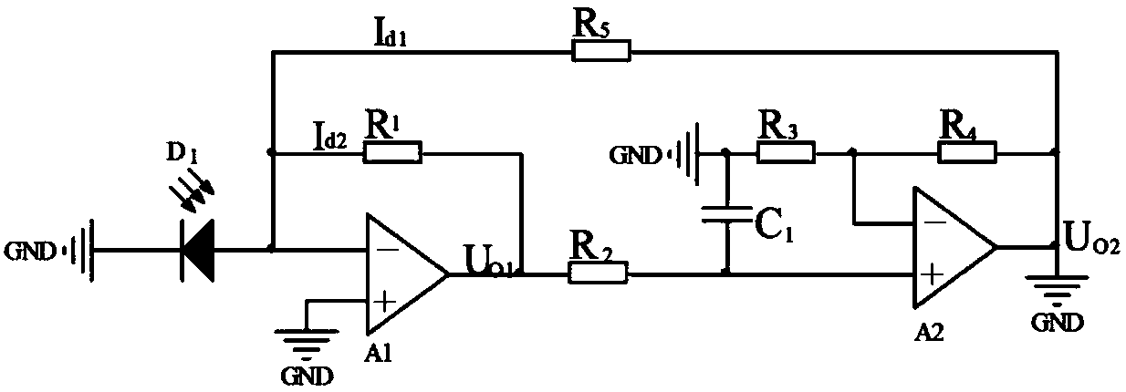
[0016] see figure 1 A photoelectric detection circuit for optical heterodyne detection includes: a photoelectric conversion diode, a transimpedance amplifier circuit, a first-order RC low-pass filter circuit, a phase proportional operation circuit and an interstage feedback circuit. The output of the said photoelectric conversion diode D1 is connected to the reverse input terminal of the operational amplifier A1 in the transimpedance amplifier circuit, the non-invertin...


PUM


Abstract

The present invention discloses a photoelectric detection circuit for optical heterodyne detection. The photoelectric detection circuit comprises a photovoltaic conversion diode, a transimpedance amplification circuit, a first-order RC low-pass filtering circuit, an in-phase proportion operational amplifier circuit and an interstage feedback circuit. The photovoltaic conversion diode is configuredto convert optical signals to current signals and output the current signals to an inverted input end of the transimpedance amplification circuit, the in-phase input end of the transimpedance amplification circuit is earthed, the output of the transimpedance amplification circuit is connected with the first-order RC low-pass filtering circuit, the first-order RC low-pass filtering circuit is connected with the in-phase input end of the in-phase proportion operational amplifier circuit, the interstage feedback circuit is connected with a resistor through the output end of the in-phase proportion operational amplifier circuit, the other end of the resistor is subjected to feedback to the input end of the transimpedance amplification circuit, and the inverted input end of the in-phase proportion operational amplifier circuit is connected with the resistor and then earthed. The photoelectric detection circuit can achieve direct current isolation and alternating current amplification functions for the optical heterodyne detection signals so as to effectively improve the optical heterodyne detection beat frequency signal contrast ratio.

Description

Technical field: [0001] The invention relates to the technical field of optical heterodyne detection circuits, in particular to a photoelectric detection circuit for optical heterodyne detection. Background technique: [0002] With the rapid development of optical detection technology, optical detection has been widely used in distance measurement, displacement measurement, speed measurement and so on. There are two main types of optical detection technology: optical direct detection and optical heterodyne detection. The direct light detection method is simple and easy to implement, but it cannot obtain all the information of the signal, and the signal-to-noise ratio is low. Optical heterodyne detection has high detection sensitivity, can obtain all information of the signal, high signal-to-noise ratio, is suitable for weak signal detection, and has good filtering performance. Large, resulting in low signal contrast. Typical acousto-optic frequency shifter frequency shift...

Claims


Application Information

Patent Timeline
IPC IPC(8): G01J1/42G01R23/14
CPCG01J1/4228G01R23/14
Inventor 张雄星吕文涛王伟陈海滨王可宁高明侯宏录
Owner XIAN TECHNOLOGICAL UNIV
Features
  • R&D
  • Intellectual Property
  • Life Sciences
  • Materials
  • Tech Scout
  • Unparalleled Data Quality
  • Higher Quality Content
  • 60% Fewer Hallucinations
Learn More