
Multiple distance point laser three dimensional close-shot imaging simulation device and simulation method

An imaging simulation and point laser technology, which is applied to the simulation device, instrument, electromagnetic wave re-radiation of space navigation conditions, etc., can solve the problem of effective verification of the laser system sensor that cannot be imaged, so as to reduce the risk of personal injury, Effect of Reducing Laser Propagation Distance

Active Publication Date: 2018-09-14
BEIJING INST OF CONTROL ENG
View PDF8 Cites 2 Cited by
  • Summary
  • Abstract
  • Description
  • Claims
  • Application Information

AI Technical Summary

Problems solved by technology

[0003] The technical problem of the present invention is: to overcome the deficiencies of the prior art, and to propose a multi-distance point laser three-dimensional close-range imaging simulator. The problem with effective verification

Method used


Image

  • Multiple distance point laser three dimensional close-shot imaging simulation device and simulation method
  • Multiple distance point laser three dimensional close-shot imaging simulation device and simulation method
  • Multiple distance point laser three dimensional close-shot imaging simulation device and simulation method

Examples


Embodiment

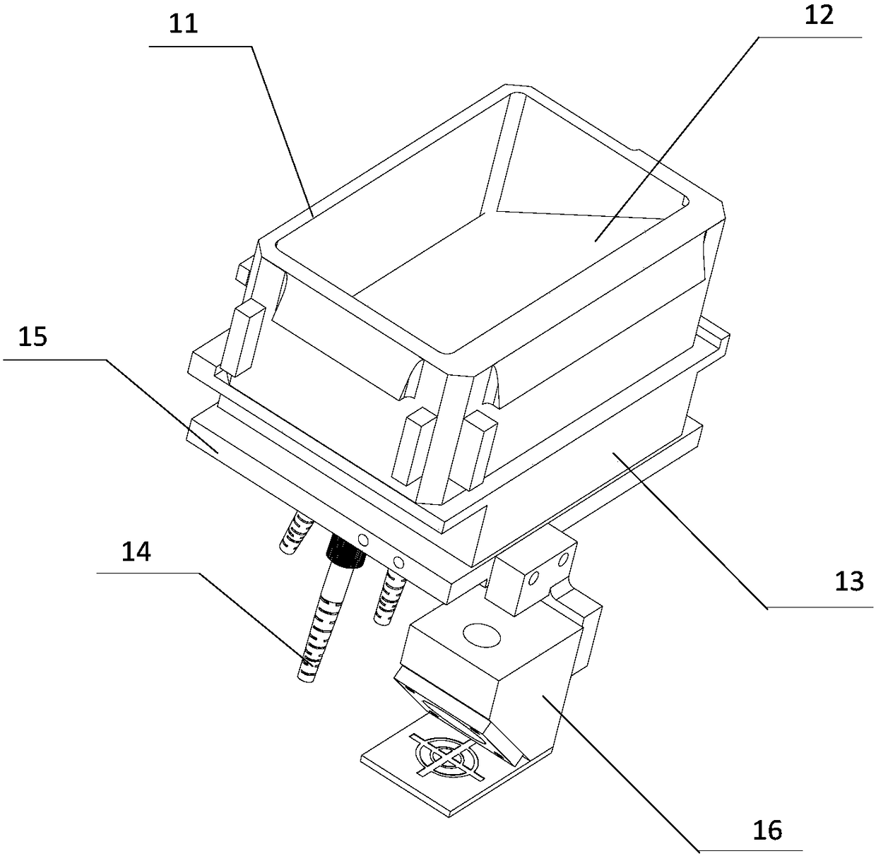
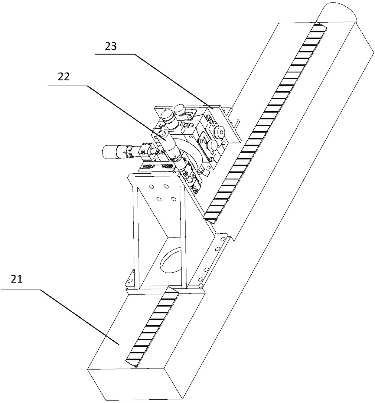
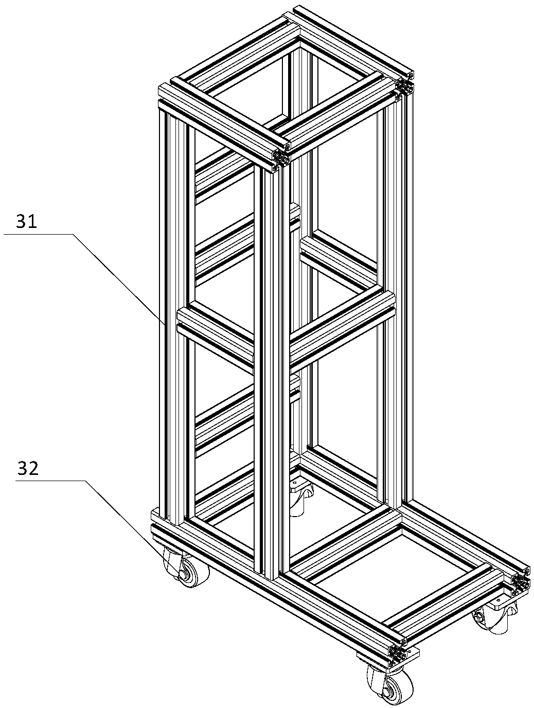
[0080] A multi-distance point laser three-dimensional close-range imaging simulator includes an embedded lens group 1, a two-dimensional adjustment mechanism 2, a wheeled carrier 3, and an integrated optical fiber group 4, such as Figure 7 shown.

[0081] Such as figure 1 As shown, the embedded lens group 1 includes an alignment tool 11, an inclined attenuation sheet 12, a lens group housing 13, a coupling mirror 14, a coupling mirror body 15 and a laser collimation system 16;

[0082] The alignment tool 11 is a hollow cuboid without a bottom and no cover, that is, the cuboid has an inner cavity, and each edge of the cuboid has a small cuboid bump on the left and right sides;

[0083] The inclined attenuation sheet 12 is a rectangular sheet, the long side of the rectangular sheet is consistent with the length of the long side of the inner cavity of the alignment tool 11, and the short side of the rectangular thin sheet is the same as the height of the inner cavity of the ali...


PUM


Abstract

The invention relates to an imaging type laser system sensor simulation device and simuation method, specifically relates to a multiple distance point laser three dimensional close-shot imaging simulation device and simulation method and belongs to the technical field of spaceflight product ground verification. Via the simulation device and the simulation method, full physical excitation signals of an imaging type laser system sensor can be output, and effectiveness of function and performance verification tests of the sensor can be greatly improved. The design method is also characterized bysimple installation debugging, high security, and convenient mobile transport.

Description

technical field [0001] The invention relates to an imaging laser system sensor simulator and a simulation method, in particular to a multi-distance point laser three-dimensional close-range imaging simulator and a simulation method, belonging to the technical field of aerospace product ground verification. Background technique [0002] The mission goal of the lunar lander is to use guidance, navigation and control technology to achieve a soft landing on the lunar surface. During the power descent process, the lunar lander uses the imaging laser system sensor to image the landing area to obtain three-dimensional elevation image data, and then the image processing module calculates and processes the three-dimensional image data to obtain the landing point information of the current landing area , so as to ensure that the lunar lander lands in a safe and flat area. Therefore, the imaging laser body sensor, as an important single machine of the lander, needs to be fully experim...

Claims


Application Information

Patent Timeline
Patent Type & Authority Applications(China)
IPC IPC(8): G01S17/89B64G7/00
CPCB64G7/00G01S17/89
Inventor 杨巍于萍王华强于洁王志文赵宇杨洁谢斌斌
Owner BEIJING INST OF CONTROL ENG
Learn More