Photovoltaic module mounting rack well adaptable to environment temperature change

A technology that adapts to the environment and temperature changes. It is applied in the direction of photovoltaic modules, photovoltaic power generation, and support structures of photovoltaic modules. It can solve problems such as poor structural stability.

Active Publication Date: 2018-09-14
SICHUAN XINGZHI ZHIHUI INTPROP OPERATION CO LTD
View PDF6 Cites 3 Cited by
  • Summary
  • Abstract
  • Description
  • Claims
  • Application Information

AI Technical Summary

Problems solved by technology

In the existing flexible support frame for photovoltaic devices, the support structure of solar photovoltaic devices is generally formed by multiple steel cables. This structure

Method used


Image

  • Photovoltaic module mounting rack well adaptable to environment temperature change
  • Photovoltaic module mounting rack well adaptable to environment temperature change
  • Photovoltaic module mounting rack well adaptable to environment temperature change

Examples


Embodiment 1

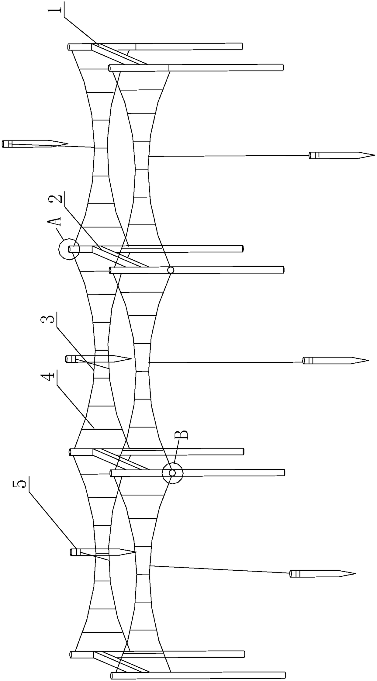
[0049] Such as Figure 1 to Figure 6 As shown in , the photovoltaic module mounting frame that can well adapt to changes in ambient temperature includes multiple poles and multiple cables connected between the poles, and the multiple cables form multiple sets of cable parts;

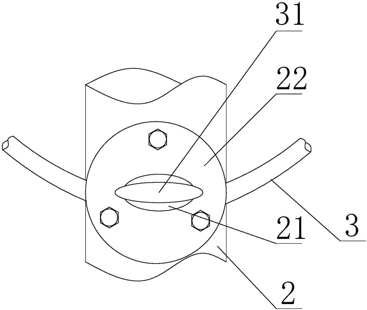
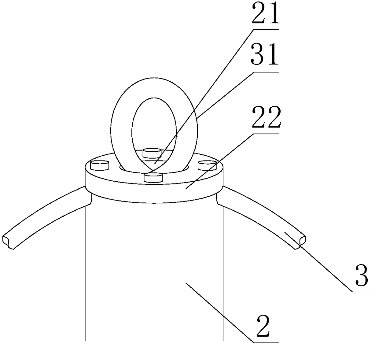
[0050] Each cable part includes two transverse stay cables 3, and the two transverse stay cables 3 on each cable part are located at different heights;

[0051] Each cable part also includes a plurality of intermediate connectors 4, each intermediate connector 4 is a rod-shaped structure with adjustable length, and the upper end of each intermediate connector 4 is fixed to the upper transverse cable 3 in the cable part. connected, the lower end of each intermediate connector 4 is fixedly connected to the lower transverse stay cable 3 in the stay cable portion;

[0052] Each intermediate connecting member 4 applies a pushing or pulling force to the transverse stay cable 3 connected to its end, so that th...

Embodiment 2

[0062] Such as Figure 1 to Figure 6 As shown, this embodiment is further limited on the basis of Embodiment 1: each upper end cable is located at a different height, and along the distance direction of the adjacent upper end cable, the height of the upper end cable in space increases or decreases successively . In this scheme, if there are N cable parts on the installation frame, then the installation frame includes N upper cable cables parallel to each other, the N upper cable cables are arranged in parallel in space, and the N upper cable cables are at different heights and Arranged in steps. By adopting this scheme, it is convenient for the photovoltaic device to obtain an inclined installation surface to meet the requirement of inclined installation of the photovoltaic device.

[0063] The number of the uprights is three or greater, and a plurality of uprights are arranged in rows or columns, and the uprights at the end of the installation frame are side uprights 1, and...


PUM


Abstract

The invention discloses a photovoltaic module mounting rack well adaptable to environment temperature change. The mounting rack comprises a plurality of vertical rods and a plurality of cables, wherein the plurality of cables constitute a plurality of cable parts; each cable part comprises two transverse cables, and two transverse cables at each cable part are located at different heights; each cable part also comprises a plurality of middle connecting pieces which adopt length-adjustable rod-like structures; in each cable part, the transverse cables at the top ends are upper end cables. The mounting rack also comprises anchoring parts, and each anchoring part comprises an anchoring nail and a spiral spring; in the cable part between any two vertical rods, the transverse cable on the lowerside is connected with one anchoring part, and each anchoring part is connected with the corresponding transverse cable through the other end of a pull cable. The mounting rack has high structural stability, can effectively guarantee support stability for a solar photovoltaic device and has good shape holding capacity in seasonal change.

Description

technical field [0001] The invention relates to the technical field of photovoltaic power generation, in particular to a photovoltaic component mounting frame that can well adapt to changes in ambient temperature. Background technique [0002] Photovoltaic power generation is a technology that directly converts light energy into electrical energy by using the photovoltaic effect at the semiconductor interface. Solar photovoltaic power generation system is a new type of power generation system that directly converts solar radiation energy into electrical energy by using the photovoltaic effect of solar cell semiconductor materials. Its core is solar photovoltaic modules, which generally include multiple photovoltaic devices. [0003] In the prior art, a solar photovoltaic power generation system generally arranges a plurality of photovoltaic devices in an array, and makes the solar photovoltaic devices face the sun as long as possible to enhance their light absorption rate an...

Claims


Application Information

Patent Timeline
IPC IPC(8): H02S20/30F24S25/50
CPCH02S20/30Y02E10/50
Inventor 龚平
Owner SICHUAN XINGZHI ZHIHUI INTPROP OPERATION CO LTD
Why Eureka
Try Eureka