
LED short-circuit protection circuit for BUCK-BOOST LED drive circuit

A short-circuit protection circuit and drive circuit technology, which is applied in the direction of electric light sources, electrical components, electroluminescent light sources, etc., can solve the problems of inductive current discharge, circuit failure, high-voltage MOSFET burnout and breakdown, etc., to reduce input power consumption , the effect of improving stability

Pending Publication Date: 2018-09-14
无锡恒芯微科技有限公司
View PDF0 Cites 0 Cited by
  • Summary
  • Abstract
  • Description
  • Claims
  • Application Information

AI Technical Summary

Problems solved by technology

Since the time of Ton_max (maximum conduction time) and Toff_max (maximum demagnetization time) is set internally, the system will work at the working state of Ton_max and Toff_max at this time. Due to the short circuit of the load LED, the system cannot When the current of the inductor is fully discharged, the current of the inductor will become larger and larger. When it increases to a certain extent, the high-voltage MOSFET will be burned and broken down, which will cause the circuit to fail.

Method used


Image

  • LED short-circuit protection circuit for BUCK-BOOST LED drive circuit
  • LED short-circuit protection circuit for BUCK-BOOST LED drive circuit
  • LED short-circuit protection circuit for BUCK-BOOST LED drive circuit

Examples


Embodiment Construction

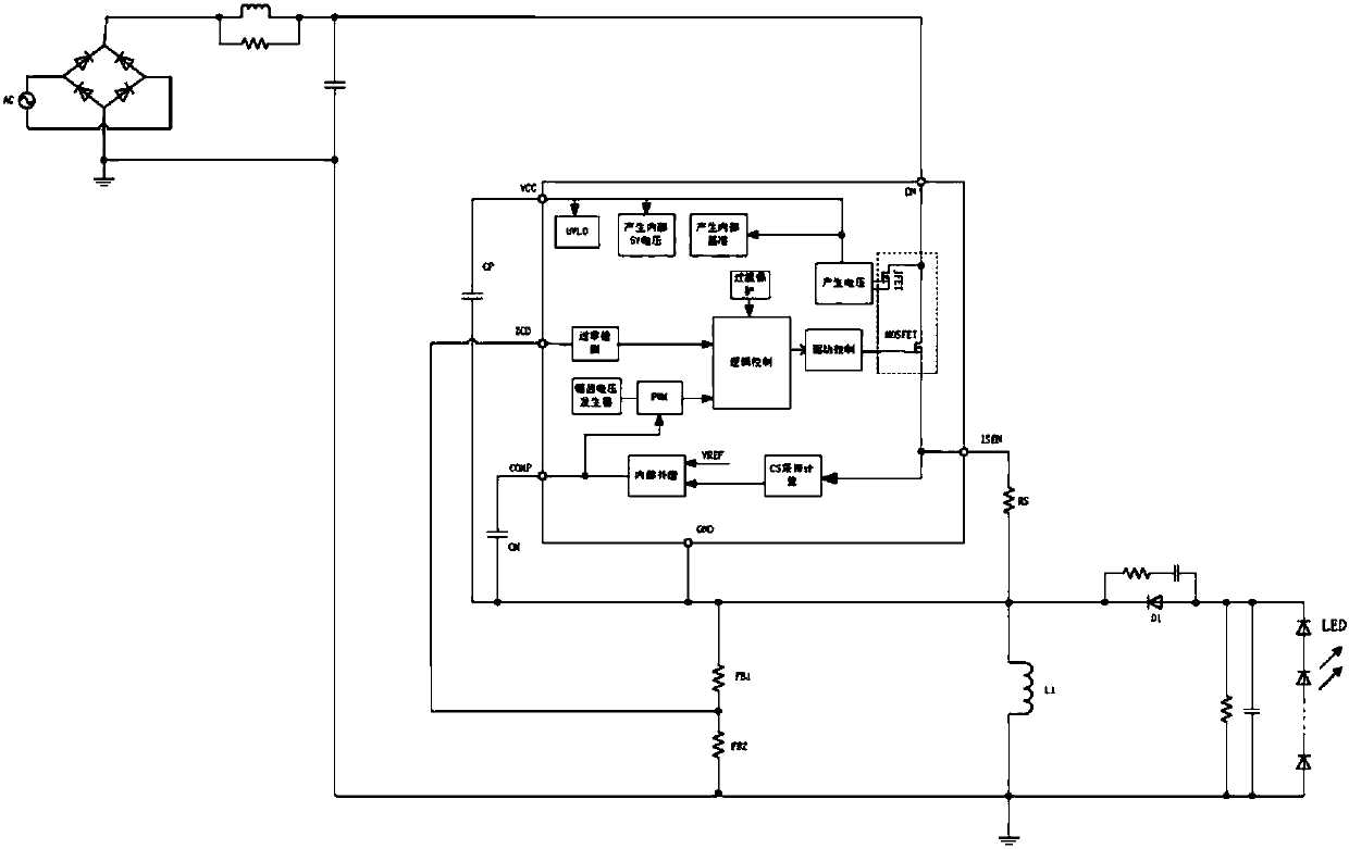
[0044] combine Figure 2 to Figure 5 , which describes a specific embodiment of the present invention in detail, but does not limit the claims of the present invention in any way.

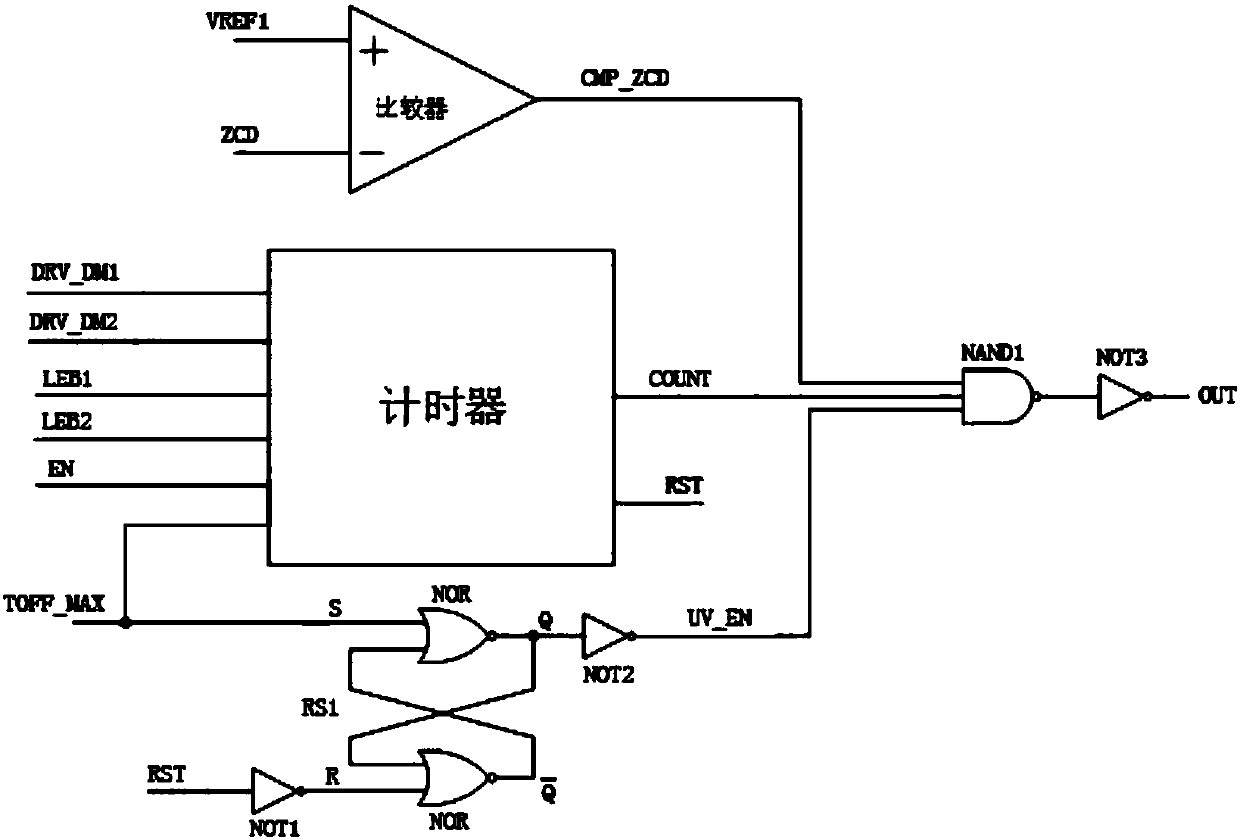
[0045] Such as figure 2 and image 3 As shown, an LED short-circuit protection circuit for BUCK-BOOST LED driving circuit, including a comparator, a timer, a first RS flip-flop RS1, a first NOT gate NOT1, a second NOT gate NOT2, and a third NOT gate NOT3 And the first NAND gate NAND1;

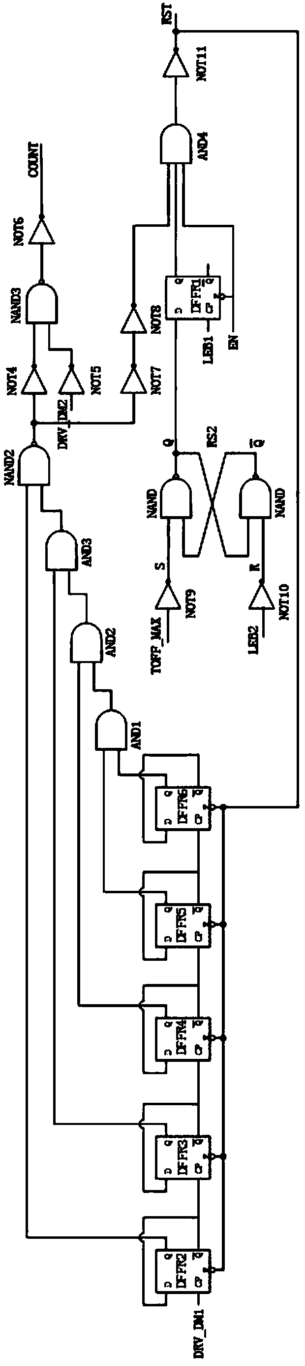
[0046] The first RS flip-flop RS1 is composed of two NOR gates, and the timer includes the first D flip-flop DFFR1, the second D flip-flop DFFR2, the third D flip-flop DFFR3, the fourth D flip-flop DFFR4, the fifth D flip-flop The device DFFR5, the sixth D flip-flop DFFR6, the second RS flip-flop RS2, the first AND gate AND1, the second AND gate AND2, the third AND gate AND3, the fourth AND gate AND4, the second NAND gate NAND2, the third NAND gate NAND3, fourth NOT gate NOT4, fifth NOT gate NOT5, sixth NOT gat...


PUM


Abstract

The present invention relates to the technical field of LED drive circuits, and especially to a LED short-circuit protection circuit for a BUCK-BOOST LED drive circuit. The LED short-circuit protection circuit comprises a comparer, a timer, a first RS trigger, a first NOT gate, a second NOT gate, a third NOT gate and a first NAND gate. The timer comprises a first D trigger, a second D trigger, a third D trigger, a fourth D trigger, a fifth D trigger, a sixth D trigger, a second RS trigger, a first AND gate, a second AND gate, a third AND gate, a fourth AND gate, a second NAND gate, a third NAND gate, a fourth NOT gate, a fifth NOT gate, a sixth NOT gate, a seventh NOT gate, an eighth NOT gate, a ninth NOT gate, a tenth NOT gate and an eleventh NOT gate. The LED short-circuit protection circuit for the BUCK-BOOST LED drive circuit improves the system stability, prevents the chip from being damaged and even bombed in a LED short-circuit condition, and reduces the system input power consumption in the LED short-circuit condition.

Description

technical field [0001] The invention relates to the technical field of LED driving circuits, in particular to an LED short-circuit protection circuit used in a BUCK-BOOST LED driving circuit. Background technique [0002] At present, most Buck-Boost LED drive circuits in the domestic market use traditional voltage technology and require an external power supply system. The positive load terminal of the LED provides the VCC voltage through resistors and diodes. Due to the needs of the market, the inventor has previously developed a BUCK-BOOST LED drive circuit powered by an integrated high-voltage JFET. This drive circuit does not require an external power supply circuit, so it is simpler in system application solutions. The change of LED LED short-circuit protection has also caused new problems. [0003] The traditional Buck-Boost LED drive circuit does not use high-voltage integration technology, and its power supply system is provided by the start-up resistor and the load...

Claims


Application Information

Patent Timeline
Patent Type & Authority Applications(China)
IPC IPC(8): H05B33/08H05B44/00
CPCH05B45/50Y02B20/30
Inventor 吴建良
Owner 无锡恒芯微科技有限公司
Learn More