Gas purifying chamber for coal mine electrical equipment

A technology for electrical equipment and clean rooms, applied to chemical instruments and methods, separation of dispersed particles, combined devices, etc.

Inactive Publication Date: 2018-09-18
XUCHANG YONGXIN ELECTRIC
View PDF0 Cites 3 Cited by
  • Summary
  • Abstract
  • Description
  • Claims
  • Application Information

AI Technical Summary

Problems solved by technology

[0004] As we all know, the gas under the coal mine is very turbid. The air not only contains flammable gas, but also contains a small amount of oil mist, water vapor and a large amount of dust. A major culprit...

Method used


Image

  • Gas purifying chamber for coal mine electrical equipment
  • Gas purifying chamber for coal mine electrical equipment
  • Gas purifying chamber for coal mine electrical equipment

Examples


Embodiment 1

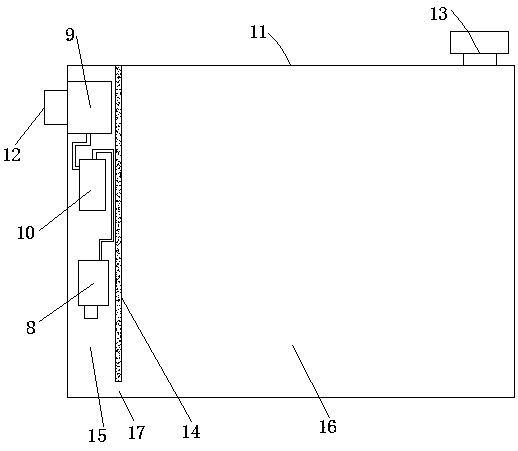
[0042] In this embodiment, the gas purification room for coal mine electrical equipment includes a sealed cavity structure with an internal space formed by a plurality of wall panels 11 butted against each other. The sealed cavity is provided with an air inlet 12 and an exhaust port. A fan 13 is provided at the mouth, and a sound insulation board 14 is arranged in the sealed cavity. The lower end surface of the sound insulation board 14 and the bottom wallboard of the sealed cavity have a certain ventilation gap 15, and the remaining end surfaces of the sound insulation board 14 are sealed with the inner wall of the sealed cavity. The sound insulation board 14 divides the space of the sealed cavity into a ventilation cavity 15 and a clean cavity 16. Coal mine electrical equipment is mainly installed in the clean cavity 16, and the ventilation cavity 15 communicates with the air inlet 12. In the ventilation cavity 15 The inner air inlet 12 is sequentially connected to the coarse...

Embodiment 2

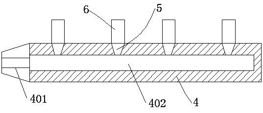
[0045] In this embodiment, except that the structure of the gas nozzle is different from that in Embodiment 1, the rest of the structures are completely the same, so only the structure of the gas nozzle is described here, such as Figure 5 As shown, the gas nozzle structure includes a screw joint 5 and a pipe body 6 connected to the screw joint. The air uniform plate 604, the buffer chamber 605, the dispersion plate 606 and the exhaust port 607, the air flow channel II501 in the screw joint and the air inlet chamber 601 realize the sealing connection, and the air uniform plate 604 is evenly equipped with several cone-shaped The vent hole 6041, the larger end of the vent hole 6041 faces the air storage chamber 603, a cotton layer is arranged in the buffer chamber 605, and a plurality of through holes are arranged on the dispersion plate 606, and the through holes are located in the dispersion It is composed of a central hole in the middle of the plate and a plurality of incline...


PUM

PropertyMeasurementUnit
Angleaaaaaaaaaa

Abstract

The invention relates to a gas purifying chamber for coal mine electrical equipment. The gas purifying chamber for the coal mine electrical equipment comprises a sealed cavity body structure with an internal space formed by abutting a plurality of wall plates, wherein a sound insulating plate is arranged in a sealed cavity body, and a certain ventilation gap is arranged between the lower end surface of the sound insulating plate and the bottom wall plate of the sealed cavity body; the other end surfaces of the sound insulating plate are sealingly connected with the inner wall of the sealed cavity body, and the space of the sealed cavity body is divided by the sound insulating plate into a ventilation cavity and a purification cavity; the ventilation cavity is communicated with an air inlet, and the air inlet in the ventilation cavity is sequentially connected with a coarse filter, a purifier and a drying box through connecting pipelines; the dirty air discharged through the air inlet is sequentially processed by the coarse filter, the purifier, the drying box, and enters the purification cavity through the ventilation gap to realize the air circulation. The gas purifying chamber can coarsely filter, purify and dry the external oily and dusty gas effectively, thereby improving the air quality in an electric control room, improving the safety of the coal mine electrical equipmentand prolonging the service life.

Description

technical field [0001] The invention relates to a structure of a coal mine electrical equipment installation room, in particular to a gas purification room for coal mine electrical equipment. Background technique [0002] At present, as the country pays more and more attention to safety issues in coal mining, some small coal mines with high pollution and poor equipment are gradually shutting down or suspending business for a long time for rectification, and large coal mining groups are also becoming more and more Pay attention to the safety management of coal mine electrical equipment, which is related to the survival of countless workers' families. [0003] The coal mine electrical equipment in the electrical control room under the coal mine is the core of the management of the entire coal mine. The safe and reliable operation of the underground electrical equipment is not only related to the safe production of the mine, but also related to the life safety of the staff. Th...

Claims


Application Information

Patent Timeline
IPC IPC(8): B01D53/26B01D53/00B01D50/00
CPCB01D53/002B01D53/265B01D50/20
Inventor 彭付强于金要郭锋
Owner XUCHANG YONGXIN ELECTRIC
Why Eureka
Try Eureka