
Receipt printer with automatic stamping function

A receipt printer and automatic technology, applied in typewriters, printing, stamping and other directions, can solve the problems of high error rate and low stamping efficiency, and achieve the effect of accurate stamping, high stamping efficiency and pollution prevention.

Inactive Publication Date: 2018-09-18
重庆华康印务有限公司
View PDF7 Cites 7 Cited by
  • Summary
  • Abstract
  • Description
  • Claims
  • Application Information

AI Technical Summary

Problems solved by technology

[0004] The purpose of the present invention is to solve the problems that the existing bills are stamped manually after being printed out, the efficiency of stamping is low, and the error rate is high

Method used


Image

  • Receipt printer with automatic stamping function
  • Receipt printer with automatic stamping function
  • Receipt printer with automatic stamping function

Examples


Embodiment Construction

[0021] The following is further described in detail through specific implementation methods:

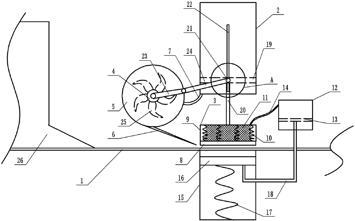
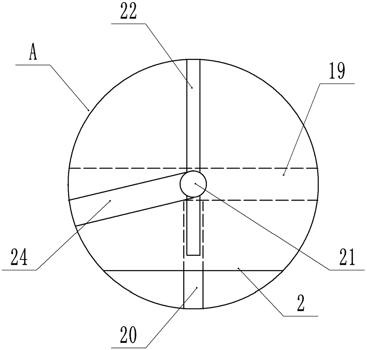
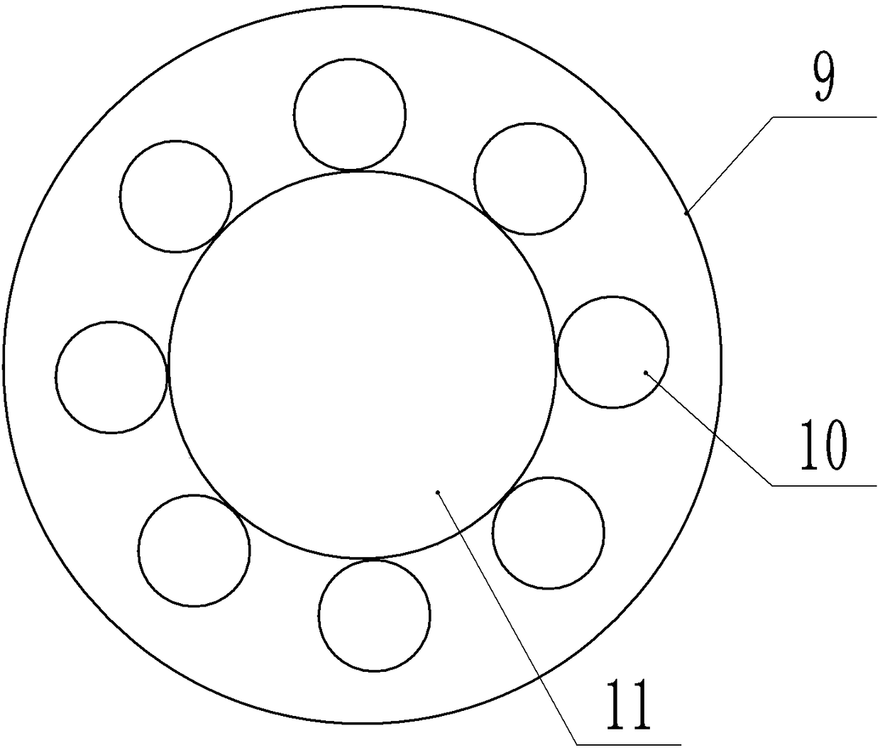
[0022] The reference signs in the drawings of the description include: belt conveyor belt 1, air cylinder 2, seal structure 3, rotating shaft 4, air roller 5, blowing nozzle 6, air pipe 7, stamping part 8, ink storage part 9, spring 10, Printing oil sponge 11, printing oil bottle 12, piston 13, printing oil pipe 14, bearing cylinder 15, bearing plate 16, compression spring 17, co-moving rod 18, slide plate 19, fixed rod 20, slide block 21, chute 22, the first A rod 23, a second rod 24, a circulation blade 25, a printer 26.

[0023] An embodiment of an automatic stamped receipt printer is basically as attached figure 1 Shown: including the motor, the frame, the belt conveyor belt 1 arranged at the paper output end of the printer 26, the stamping mechanism arranged on the frame above the belt conveyor belt 1, and the bearing mechanism arranged on the frame below the belt conveyor belt...


PUM


Abstract

The invention relates to the technical field of receipt processing and particularly discloses a receipt printer with an automatic stamping function. The receipt printer comprises a motor, a rack, a belt conveyor arranged at the paper discharge end of the printer, a stamping mechanism arranged at the position, above the belt conveyor, of the rack, and a bearing mechanism arranged at the position, below the belt conveyor, of the rack. The stamping mechanism comprises an inflator fixedly connected with the rack, a stamp structure slidably connected with the inflator, and a rotary shaft rotationally connected with the rack, wherein the inflator is provided with an air inlet, a one-way valve is arranged at the air inlet, a sliding plate is slidably connected in the inflator, a fixing rod is connected between the sliding plate and the stamp structure, and the rotary shaft can drive the stamp structure to make vertical reciprocating motion through the fixing rod. According to the receipt printer with the automatic stamping function, the stamp structure is driven by the rotary shaft to stamp a receipt, the receipt can be continuously and automatically stamped by cooperating with the belt conveyor and the printer, the stamping efficiency is high, and stamping is accurate.

Description

technical field [0001] The invention relates to the technical field of bill processing. Background technique [0002] A bill is a paper print with a certain size. The bills currently used are usually printed in multiple continuous strips, and the perforations punched by the punching machine between each sheet form a cutting line or an integrated structure. After the printing is completed, it usually needs to be stamped, and the special stamp of the ticket is stamped at the designated position, so that the ticket can be used effectively. [0003] However, the existing printers and stamping equipment are usually carried out separately. After the printing is completed, manual stamping is performed manually. Due to the poor control of manual stamping, the clarity of stamping is uneven, the position of stamping is inconsistent, and the error rate is high, which may directly cause some bills to become invalid. The invalid ones need to be reprinted and sorted, which adds more time...

Claims


Application Information

Patent Timeline
Patent Type & Authority Applications(China)
IPC IPC(8): B41K3/04B41J3/44B41K3/44B41K3/62
Inventor 吴仁本
Owner 重庆华康印务有限公司
Learn More