Manipulator for drill floor

A technology for manipulators and drill floors, which is applied to drill pipes, drill pipes, and drilling equipment. It can solve the problems of low efficiency of drill pipes entering rat holes, high personnel safety risks, and high labor intensity, so as to reduce operating personnel and control safety. Risk, the effect of reducing labor intensity

Pending Publication Date: 2018-09-18
杜江
View PDF26 Cites 4 Cited by
  • Summary
  • Abstract
  • Description
  • Claims
  • Application Information

AI Technical Summary

Problems solved by technology

[0003] However, the existing pipe string movement on the drill floor is mainly driven by manpower, and the drill pipe entering the rat hole is mainly lifted by a pneumatic winch. The traditional operation method has a large amount of labor, high labor intensity, and high personnel safety risks. Disadvantages such as low rathole efficiency

Method used


Image

  • Manipulator for drill floor
  • Manipulator for drill floor
  • Manipulator for drill floor

Examples


Embodiment Construction

[0036] The present invention will be described in detail below in conjunction with the accompanying drawings and specific embodiments.

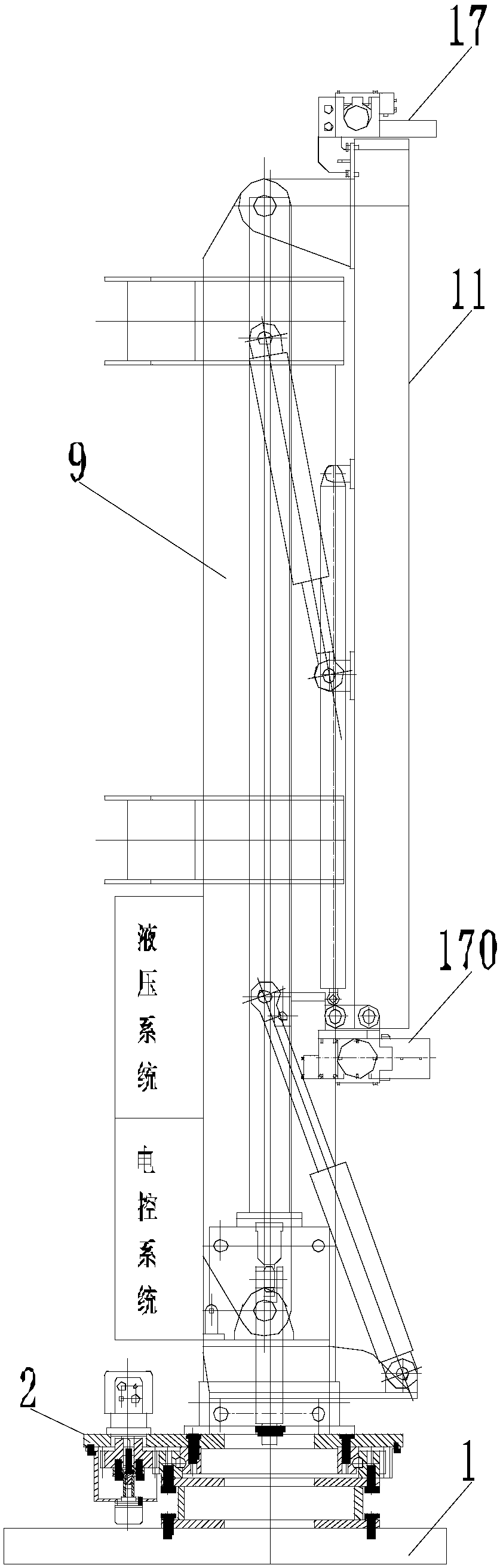
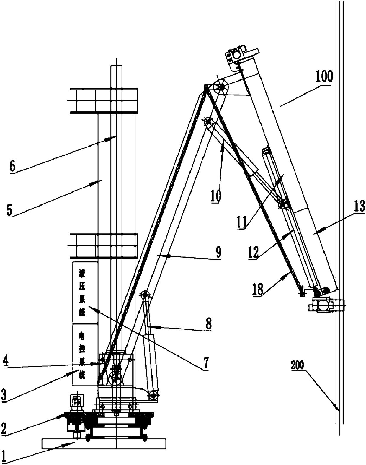
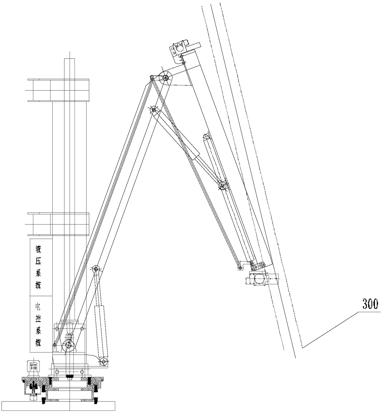
[0037] see Figure 1 to Figure 4 As shown, the present invention provides a drill floor manipulator, including a horizontal moving guide rail 1, a slewing support 2, a moving slider 4, a vertical moving guide rail 5, an inner moving arm 9, an outer moving arm 100 and a link mechanism 18.

[0038] The horizontal moving guide rail 1 is fixedly connected with the drill floor surface, the slewing bearing 2 is installed on the horizontal moving guide rail 1, and the vertical moving guide rail 5 arranged vertically is connected with the slewing bearing 2, which forms an integral column for the multifunctional manipulator; the vertical moving guide rail 5 can Rotate relative to the slewing bearing 2.

[0039] The moving slider 4 is installed in the vertical moving guide rail 5, the fixed end and the movable end of the first oil cylinder 6 are fixed...


PUM


Abstract

The invention discloses a manipulator for a drill floor. A horizontal moving guide rail is fixedly connected with the surface of the drill floor, a rotary bearing is installed on the horizontal movingguide rail, and a vertically arranged vertical moving guide rail is connected with the rotary bearing. A moving slide block is installed in the vertical moving guide rail, and the vertical moving guide rail and the moving slide block are correspondingly and fixedly connected to the fixed end and the movable end of a first oil cylinder. The moving slide block is hinged to the bottom of an inn moving arm, and the fixed end and the movable end of a second oil cylinder are correspondingly hinged to the middle and low parts of the moving slide block and the inner moving arm. The top of the inner moving arm is hinged to the top of the upper part of a moving arm, the fixed end of a third oil cylinder is hinged to the upper part of the inner moving arm, and the movable end of the third oil cylinder is hinged to the middle of the upper part of the moving arm. The manipulator can realize the automation of main work such as the movement of a pipe column of the surface of the drill floor, the buffering when the pipe column enters the drill floor to reach a wellhead and the rattling of the pipe column (drill pipe), and the problems that the current movement of the pipe column of the drill floor depends on manpower and multiple devices to work dispersedly are solved.

Description

technical field [0001] The invention belongs to the technical field of oil and gas engineering drilling equipment, and in particular relates to a drill floor manipulator capable of realizing the displacement of a pipe string on the drill floor surface and the lowering of a drill pipe (into a mouse hole) during oil and gas exploitation. Background technique [0002] Nowadays, in the field of drilling equipment for oil and gas exploration, with the continuous improvement of safety requirements and the increase of personnel costs, there are more and more demands for multifunctional manipulators on the drill floor, which are fully automatic, high efficiency, low energy consumption, remote control, It is an inevitable development trend to replace manual multi-functional manipulators for drill floor strings. [0003] However, the existing pipe string movement on the drill floor is mainly driven by manpower, and the drill pipe entering the rat hole is mainly lifted by a pneumatic w...

Claims


Application Information

Patent Timeline
Patent Type & Authority Applications(China)
IPC IPC(8): E21B19/14
CPCE21B19/14
Inventor 杜江
Owner 杜江
Why Eureka
Try Eureka