Catalytic device for high-power distributed energy tail gas purification DeNOx system

A technology for distributed energy and exhaust gas purification, which is applied in the direction of exhaust devices, noise reduction devices, engine components, etc., and can solve the problems of scattered distributed energy layout, difficulty in centralized treatment of exhaust gas, complex system structure, etc.

Pending Publication Date: 2018-09-18
NANJING IKAKAT EMISSIONS TECH CO LTD
View PDF4 Cites 2 Cited by
  • Summary
  • Abstract
  • Description
  • Claims
  • Application Information

AI Technical Summary

Problems solved by technology

[0003] 1. The layout of distributed energy is relatively scattered, and it is relatively difficult to treat exhaust gas in a centralized manner; 2. Due to the differences in the environment and fuel used in distributed energy, the concentration of NOx pollutants in exhaust gas produced by different units is not the same, and it is difficult for the engine to leave the factory. 3. Most of the distributed energy engine units use imported engine products, and it is difficult for the exhaust gas purification system to obtain engine working status information; 4. Most of the existing distributed energy units have been put into operation, and the new exhaust gas purification system has been added. The system cannot affect the operation and layout of the original system; 5. Individual distributed energy units use the vehicle SCR system for NOx purification, which is limited by the level of the vehicle SCR system itself, and often requires multiple sets of vehicle SCR systems to meet the requirements. Requirements; 6. The traditional exhaust gas purification system of distributed energy units uses PLC to control the system, which requires specific power supply and distribution and control cabinets, motors and water pumps to complete the system work. The system structure is complex and costly

Method used


Image

  • Catalytic device for high-power distributed energy tail gas purification DeNOx system
  • Catalytic device for high-power distributed energy tail gas purification DeNOx system
  • Catalytic device for high-power distributed energy tail gas purification DeNOx system

Examples


Embodiment Construction

[0020] The present invention will be further described in detail below in conjunction with specific embodiments.

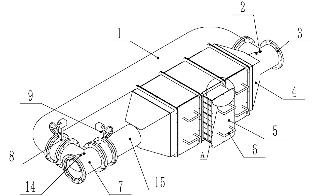
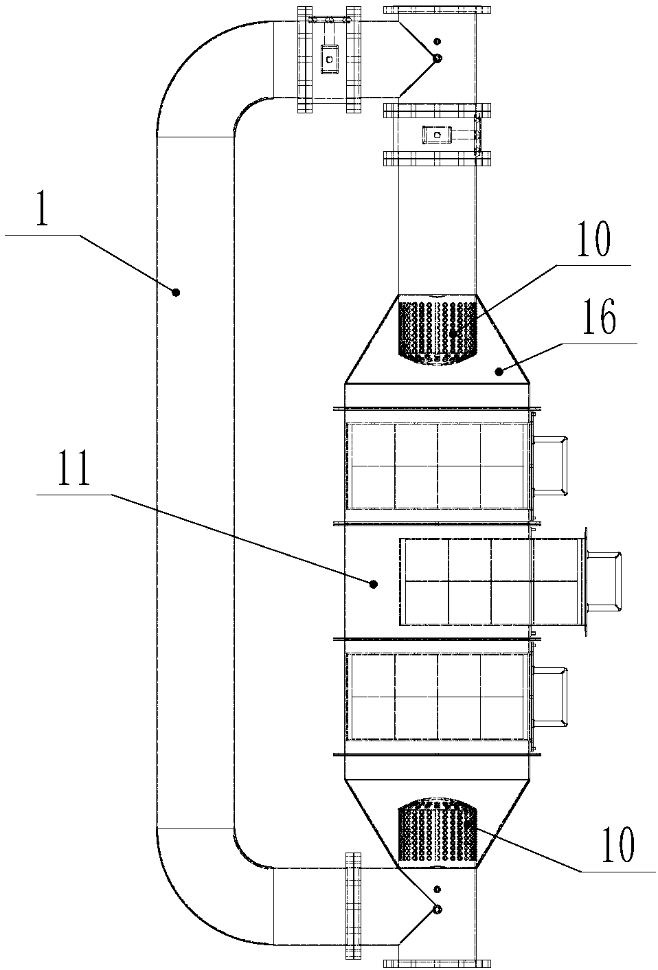
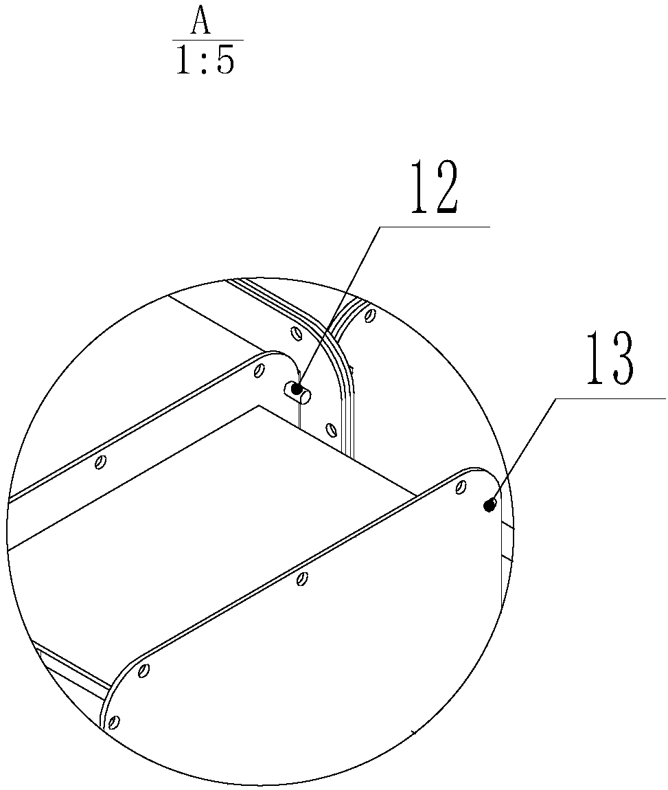
[0021] Such as Figure 1 to Figure 3 The catalytic device for a high-power distributed energy exhaust purification DeNOx system shown includes a detachable catalytic module 5, an air inlet joint 7, an air outlet joint 3, a muffler 10, a sensor seat 2, a urea nozzle mounting seat 14, a main Through butterfly valve 9, bypass butterfly valve 8, catalytic module installation box 4 and maintenance bypass pipe 1; inlet joint 7 and outlet joint 3 are three-way connection pipe joints, and each outlet end has its own connecting flange, which is convenient Install.

[0022] Both the main passage butterfly valve 9 and the bypass butterfly valve 8 are D373H / D673H / D973H triple eccentric wafer butterfly valves or D643H triple eccentric flange butterfly valves.

[0023] The maintenance bypass pipe 1 is U-shaped, and its two ends are provided with connecting flanges.

[0024] ...


PUM


Abstract

The invention discloses a catalytic device for a high-power distributed energy tail gas purification DeNOx system. An inlet connector and an outlet connector are correspondingly connected with the twoends of a catalytic module mounting box; a bypass butterfly valve is mounted between the inlet connector and a repair bypass pipe; a main-pass butterfly valve is mounted between the inlet connector and the catalytic module mounting box; a carbamide nozzle mounting base is mounted on the inlet connector; sensor seats are correspondingly mounted on the inlet connector and the outlet connector; mufflers are correspondingly mounted at the two ends of the catalytic module mounting box; and a dismountable catalytic module is mounted in the catalytic module mounting box. The catalytic module of thecatalytic device is arranged by adopting a modular assembling mode, and a catalytic cavity fitting with the catalytic module can be flexibly configured according to the requirements of different distributed energy units, so that the effective cooperation between energy tail gas systems in different powers with catalyst volumes in corresponding equivalent weights is achieved.

Description

technical field [0001] The invention relates to the technical field of engine tail gas treatment, in particular to a catalytic device for a high-power distributed energy tail gas purification DeNOx system. Background technique [0002] With the continuous development of distributed energy technology, more and more distributed energy sources such as landfill gas and natural gas have been utilized, providing a large amount of heat and power resources for the production and life of industrial society. However, with the use of these high-power gas-fired units, the large amount of NOx (nitrogen oxides) pollutants produced during their work has also received more and more attention. According to the emission indicators of atmospheric environmental pollutants formulated by the national and local environmental protection departments, the NOx contained in the tail gas of distributed energy sources also needs to be purified. The traditional distributed energy exhaust gas treatment me...

Claims


Application Information

Patent Timeline
IPC IPC(8): F01N3/20F01N3/28F01N1/08F01N13/08
CPCF01N1/082F01N3/208F01N3/28F01N13/08
Inventor 熊飘洋杨曦李科韩丰阳闫政胡广胡飞许玲玲
Owner NANJING IKAKAT EMISSIONS TECH CO LTD
Why Eureka
Try Eureka