
A motor stator rotor splitting device

A technology for the stator and rotor of a motor, which is used in electromechanical devices, manufacturing of motor generators, electrical components, etc., can solve the problems of inflexibility, less consideration for easy operation, and difficulty in taking out the rotor assembly, so as to avoid scratches and damage, and is convenient for Manual operation, the effect of saving manpower

Active Publication Date: 2020-01-17
HEFEI JEE INTELLIGENT EQUIP CO LTD
View PDF5 Cites 0 Cited by
  • Summary
  • Abstract
  • Description
  • Claims
  • Application Information

AI Technical Summary

Problems solved by technology

[0003] In the existing technology, when disassembling the motor and separating the stator assembly and the rotor assembly, simple tooling is often used to position the stator assembly, and then the rotor of the motor is separated from the stator by horizontal or vertical drawing. The tooling is not flexible enough, the centering effect is poor, it is easy to damage the motor stator coil, and it is more laborious for the operator
The disengaged rotor is not easy to lift out
The existing technology only considers the separation of the rotor assembly and the stator assembly of the motor, and less consideration is given to the convenience of operation in the disassembly process, saving time and effort; and the damage of the rotor assembly and the stator assembly is easy to occur; separation The rear rotor assembly is also more difficult to remove

Method used


Image

  • A motor stator rotor splitting device
  • A motor stator rotor splitting device
  • A motor stator rotor splitting device

Examples


Embodiment Construction

[0029] The embodiments of the present invention are described in detail below. This embodiment is implemented on the premise of the technical solution of the present invention, and detailed implementation methods and specific operating procedures are provided, but the protection scope of the present invention is not limited to the following implementation example.

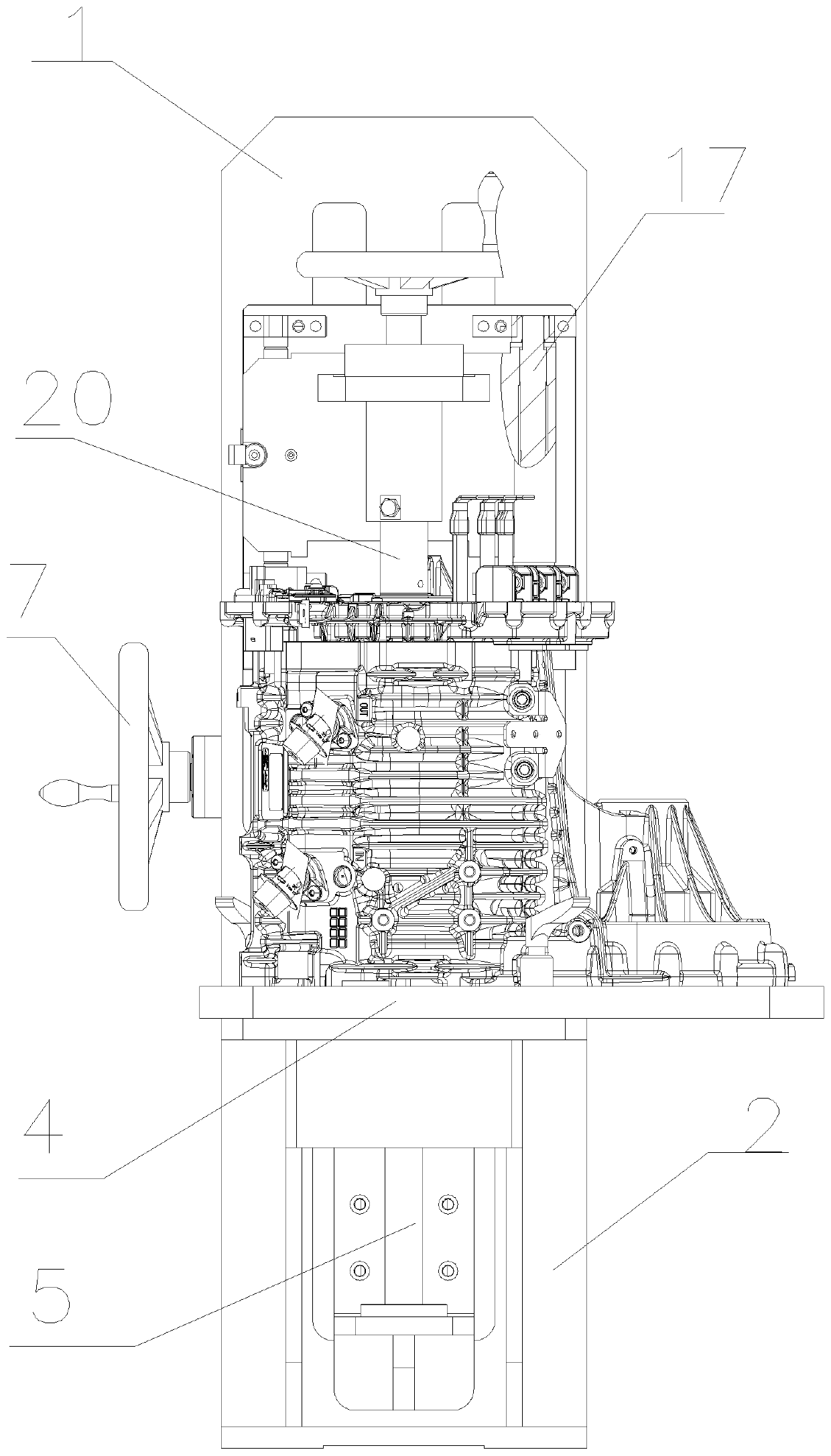
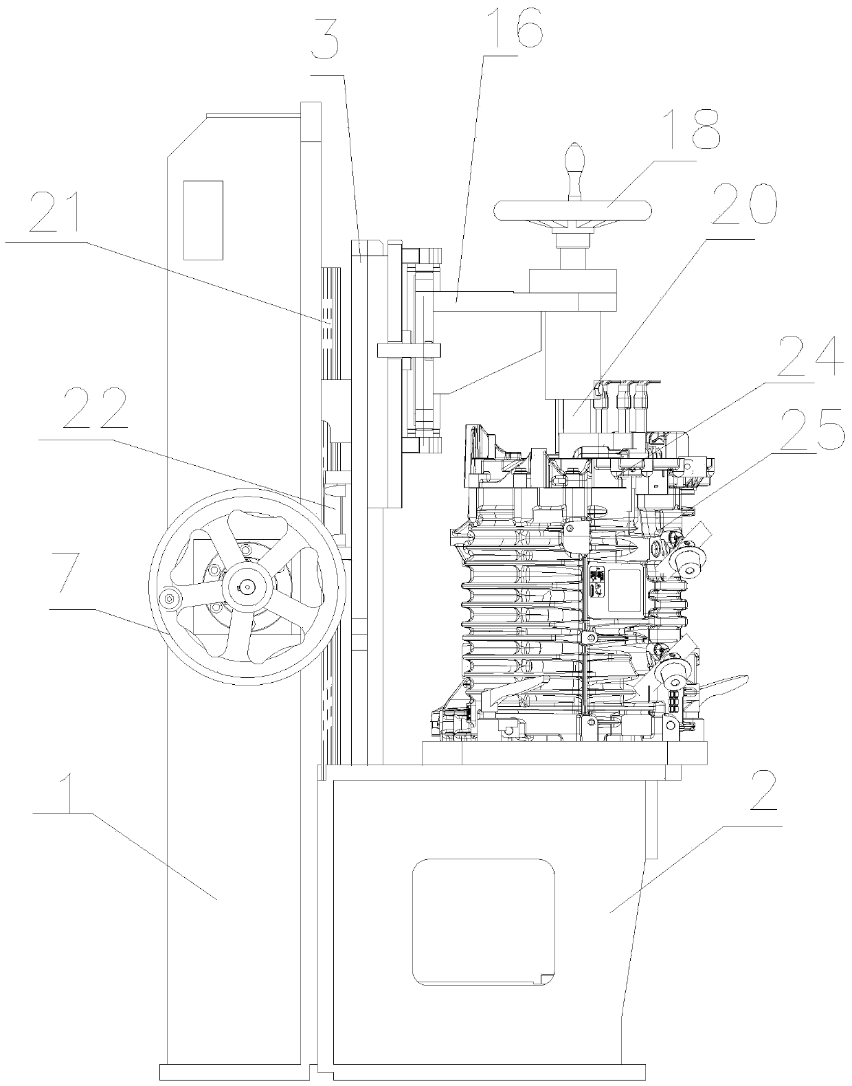
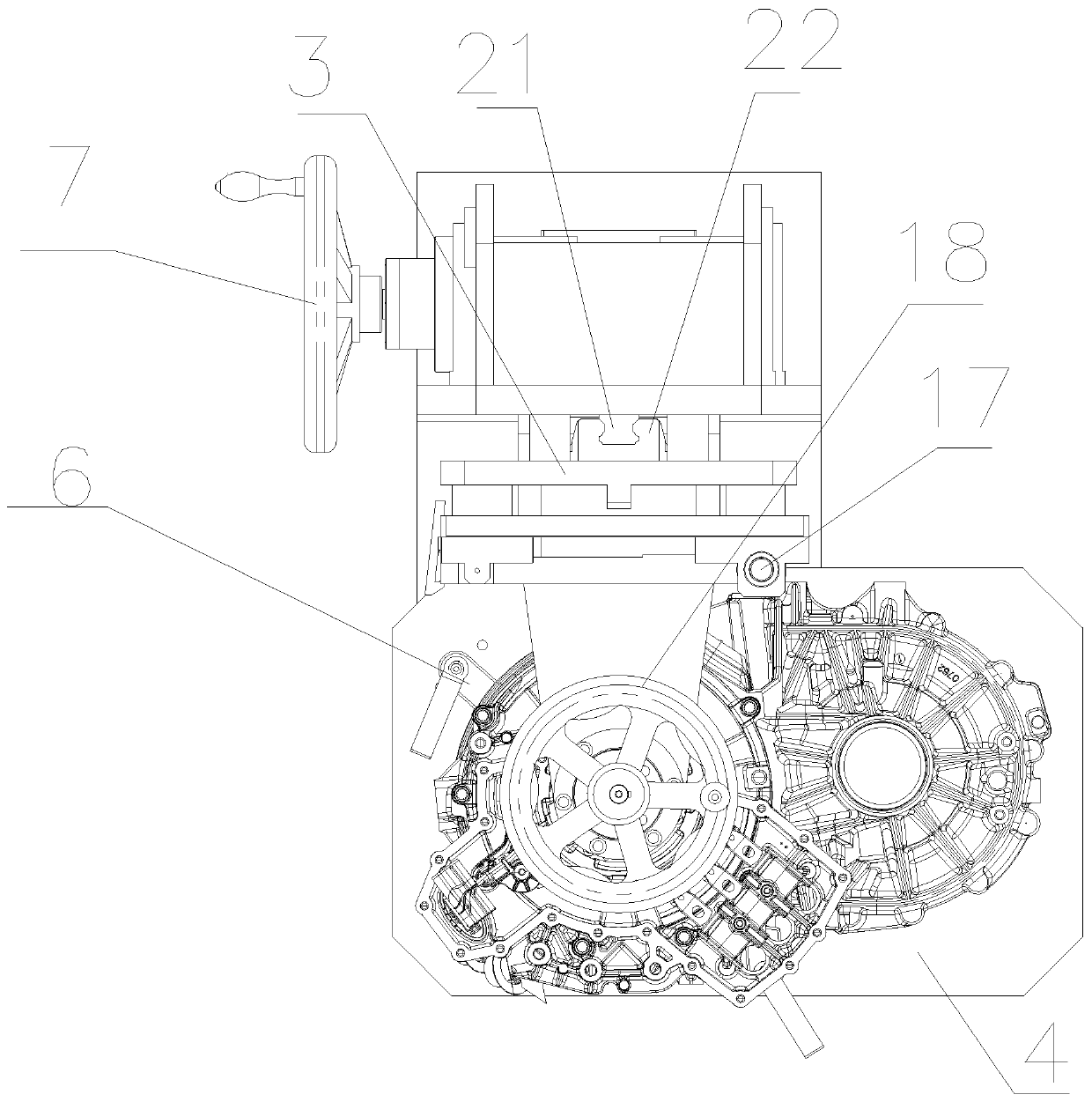
[0030] see Figure 1 to Figure 9 , this embodiment discloses a motor stator rotor splitting device, including a frame, the frame is divided into a horizontal frame 2 and a vertical frame 1, the horizontal frame 2 of the frame is provided with a horizontal work surface 4, the work surface 4 It is used to place the motor to be disassembled. The motor includes a stator assembly 25 and a rotor assembly 24. The center of the rotor assembly 24 is provided with a motor shaft 26, and the working surface 4 is provided with a clamp for compressing the stator assembly 25 of the motor. mechanism, the pressing mechanism can be...


PUM


Abstract

The invention discloses a splitting device of a stator and a rotor of a motor. The splitting device comprises a rack. A work table top is arranged on the rack. A vertical sliding bench is slidably arranged on one side of the work table top. An upper positioning device and a lower positioning device are arranged on upper and lower ends of the vertical sliding bench. The upper positioning device comprises an upper positioning support and an upper positioning support rod. The upper positioning support is rotatably arranged on the upper end of the vertical sliding bench and is capable of rotatingin the horizontal plane. The upper positioning support rod is arranged on the upper positioning rack and vertically stretches downwards. The upper positioning support rod is driven to up-down move inthe vertical direction through a second driving mechanism. The lower positioning device comprises a lower positioning support rod which is arranged on the lower end of the vertical sliding bench. Thelower positioning support rod and the upper positioning support rod are coaxially arranged. Compared with the prior art, the splitting device is advantageous in that it is ensured that a rotor assembly is separated from a stator assembly along the direction of the axis all the time, so rubbing and damage are avoided; and splitting is convenient to carry out and time and labor are saved.

Description

technical field [0001] The invention relates to the technical field of mechanical devices, in particular to a motor stator rotor splitting device. Background technique [0002] During the trial production or mass production of new energy motor products, during the quality inspection, it will be found that the assembly is unqualified. If the stator or rotor part is unqualified at this time, it is necessary to use special tooling to separate the stator assembly and the rotor assembly. It is convenient for troubleshooting and subsequent maintenance of quality problems. Since the stator assembly and the rotor assembly are assembled together by a special press-fitting mechanism, there are coaxial requirements and a certain cooperating force when the two are assembled together, which requires that the stator assembly be disassembled. The separation from the rotor assembly is also separated in the coaxial state to avoid scratching between the stator and the rotor and damage the st...

Claims


Application Information

Patent Timeline
Patent Type & Authority Patents(China)
IPC IPC(8): H02K15/00
CPCH02K15/0006
Inventor 刘蕾石爱文姚雨龙汪波任永强
Owner HEFEI JEE INTELLIGENT EQUIP CO LTD
Learn More