Method for three-box casting of large movable beam and movable column planer type milling machine lathe bed

A technology of gantry milling machine and milling machine, which is applied to casting molding equipment, casting molds, casting mold components, etc., can solve the problems of slow production efficiency of milling machines, and achieve the effect of improving production efficiency and avoiding dislocation phenomenon.

Inactive Publication Date: 2018-09-21
芜湖久弘重工股份有限公司
View PDF6 Cites 0 Cited by
  • Summary
  • Abstract
  • Description
  • Claims
  • Application Information

AI Technical Summary

Problems solved by technology

[0005] The purpose of the present invention is to provide a three-box casting method for a large-scale moving beam moving column gantry milling machine bed, which is laid by multi-point shunting straight-in pipelines, and then using the shuntin

Method used


Image

  • Method for three-box casting of large movable beam and movable column planer type milling machine lathe bed
  • Method for three-box casting of large movable beam and movable column planer type milling machine lathe bed

Examples


Embodiment 1

[0027] The present invention provides such figure 1 A three-box casting method for the bed of a large-scale moving beam moving column gantry milling machine includes the following manufacturing methods:

[0028] Step 1: Milling machine design: According to the structural characteristics, technical requirements and production model of the casting, determine the casting plan and manufacture the corresponding milling machine mold design drawing;

[0029] Step 2: Milling machine mold production: According to the milling machine mold drawing designed in step 1, the milling machine mold is produced, and the injection pipe is fixed around the top of the milling machine mold, and the injection pipe is set on the top of the injection pipe. input connection;

[0030] Step 3: Laying of multi-point split-flow straight-in pipes: After step 2 is completed, according to the design drawing of the milling machine mold designed in step 1, lay split-flow straight-in pipes around the milling mac...

Embodiment 2

[0035] The difference with embodiment 1 is:

[0036] In step 1, the milling machine mold design drawing is drawn by the computer and stored in the computer, which is beneficial to avoid data loss and provide data comparison for later detection and maintenance;

[0037] In step 2, there are 4 groups of plastic injection pipes, of which 1 group is provided at the top of both ends of the injection molding pipe and 1 group is respectively provided at the top of the middle and both sides of the injection molding pipe. ;

[0038] In step 4, when the molten steel is injected, 4 sets of plastic tubes are injected simultaneously, and when the injection is performed, the vibrator is used to vibrate the molten steel in the mold of the milling machine at the same time, so as to avoid the formation of bubbles when the molten steel is injected, and the bubbles When the molten steel is solidified, hollowing will occur inside the milling machine, which will affect the quality of the milling ...

Embodiment 3

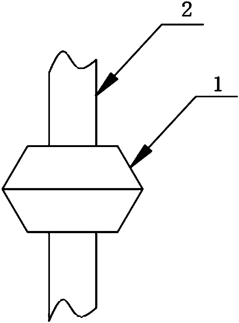
[0042] The present invention provides such figure 2 The shown is a fixed sleeve for preventing misalignment of the direct-flow pipeline, which includes a fixed sleeve 1 and a main body 2 of the direct-flow pipeline. The fixed sleeve 1 includes an upper butt joint surface cavity and a lower joint surface cavity. It includes an upper diversion straight-in pipeline and a diversion straight-in pipeline, the upper diversion straight-in pipeline and the lower diversion straight-in pipeline are integrally arranged, the top of the upper butt joint surface cavity is fixedly connected to the bottom of the upper diversion direct inflow pipeline, and the lower butt joint surface cavity The bottom is fixedly connected with the top of the direct inlet pipe of the lower diversion;

[0043] The shape of the upper branch direct-inflow pipe and the lower branch direct-inlet pipe is set as a circular platform, and the inside of the fixed sleeve 1 is set as a hollow structure.

[0044] Benefici...


PUM


Abstract

The invention discloses a method for three-box casting of a large movable beam and movable column planer type milling machine lathe bed. The method comprises the following manufacturing methods including milling machine design, milling machine die production, multi-point flow dividing straight-into pipeline pavement, pouring and forming. According to the casting structure features, technique requirements and production types, a casting scheme is determined, and a corresponding milling machine die design drawing is manufactured; according to the designed milling machine die drawing paper, a milling machine die is produced, and an injection molding pipeline is fixedly arranged on the periphery of the top of the milling machine die; and a plastic inlet pipe is arranged on the top of the injection molding pipeline, and the output end of the plastic inlet pipe is connected with the input end of the injection molding pipeline. Through the arrangement of a flow dividing straight-into pipeline, molten iron can be better synchronously injected into the milling machine die in a multi-point manner; and compared with single pipeline molten iron injection, the injection speed of the molten ironcan be increased by at least four or more times, the time spent on pouring is greatly shortened, and accordingly the production efficiency is improved.

Description

technical field [0001] The invention relates to the technical field of milling machine casting, in particular to a three-box casting method for a large moving beam moving column gantry milling machine bed. Background technique [0002] A milling machine is a machine tool that uses a milling cutter to mill a workpiece. It mainly refers to a machine tool that uses a milling cutter to process various surfaces on a workpiece. Usually the rotation of the milling cutter is the main movement, and the movement of the workpiece and the milling cutter is the feed movement. It can process planes, grooves, various curved surfaces, gears, etc. The earliest milling machine was a horizontal milling machine created in 1818 by American E. Whitney. [0003] The milling machine is a machine tool with a wide range of uses. It can process planes, grooves, toothed parts, spiral surfaces and various curved surfaces on the milling machine. In addition, it can also be used to process the surface ...

Claims


Application Information

Patent Timeline
IPC IPC(8): B22C9/22B22C9/08
CPCB22C9/22B22C9/082
Inventor 艾明何文东姬唱
Owner 芜湖久弘重工股份有限公司
Why Eureka
Try Eureka