Wearable body weight support type walking aiding device

A walking assist and support technology, applied in manipulators, program-controlled manipulators, manufacturing tools, etc., can solve the problems of immature weight-loss walking assist machines, lack of advanced functional products, and difficulty in walking for the elderly, and achieve large-scale applications. value, improve walking efficiency, and reduce energy consumption

Active Publication Date: 2018-09-21
UNIV OF SCI & TECH OF CHINA
View PDF5 Cites 8 Cited by
  • Summary
  • Abstract
  • Description
  • Claims
  • Application Information

AI Technical Summary

Problems solved by technology

[0003] In the face of urgent social needs and huge social groups, domestic and foreign academic institutions have not yet matured the research on weight-loss walking assisting machines, and there is a lack of products with advanced functions in the market. Therefore, a new type of weight-loss walking assisting machine is developed to solve the The problem of walking difficulties has important social significance and broad market prospects

Method used


Image

  • Wearable body weight support type walking aiding device
  • Wearable body weight support type walking aiding device
  • Wearable body weight support type walking aiding device

Examples


specific Embodiment approach

[0027] The preferred embodiment of the wearable body weight supporting walking aid device of the present invention is:

[0028] Including seat cushion, track assembly, control device, thigh shell, calf assembly, calf shell, I-shaped connecting rod, rotating assembly, shoes, plantar force sensor, connecting frame, Teflon rope, battery, encoder, motor, gyroscope, spring Groups, Pulleys, Gears, Thigh Links, Kvaser, Drivers, Rotary Shafts, Knob Handles, Knee Springs, Sliders;

[0029] The track assembly is connected to the lower end of the seat cushion through the spring set, the upper end of the thigh link is meshed with the track assembly through the gear, and the pulley is fixed on the track assembly through bolt connection;

[0030] The thigh casing is fixed on the thigh connecting rod through bolt connection, and the battery and the control device are respectively installed on the thigh casing;

[0031] The lower end of the thigh link is connected to the lower leg assembly t...

specific Embodiment

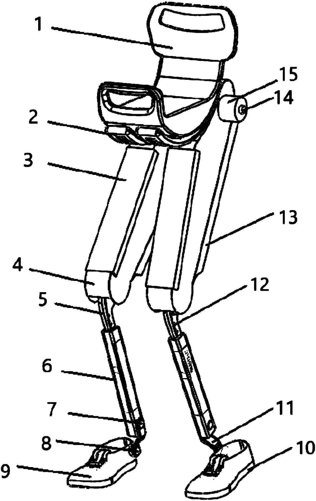
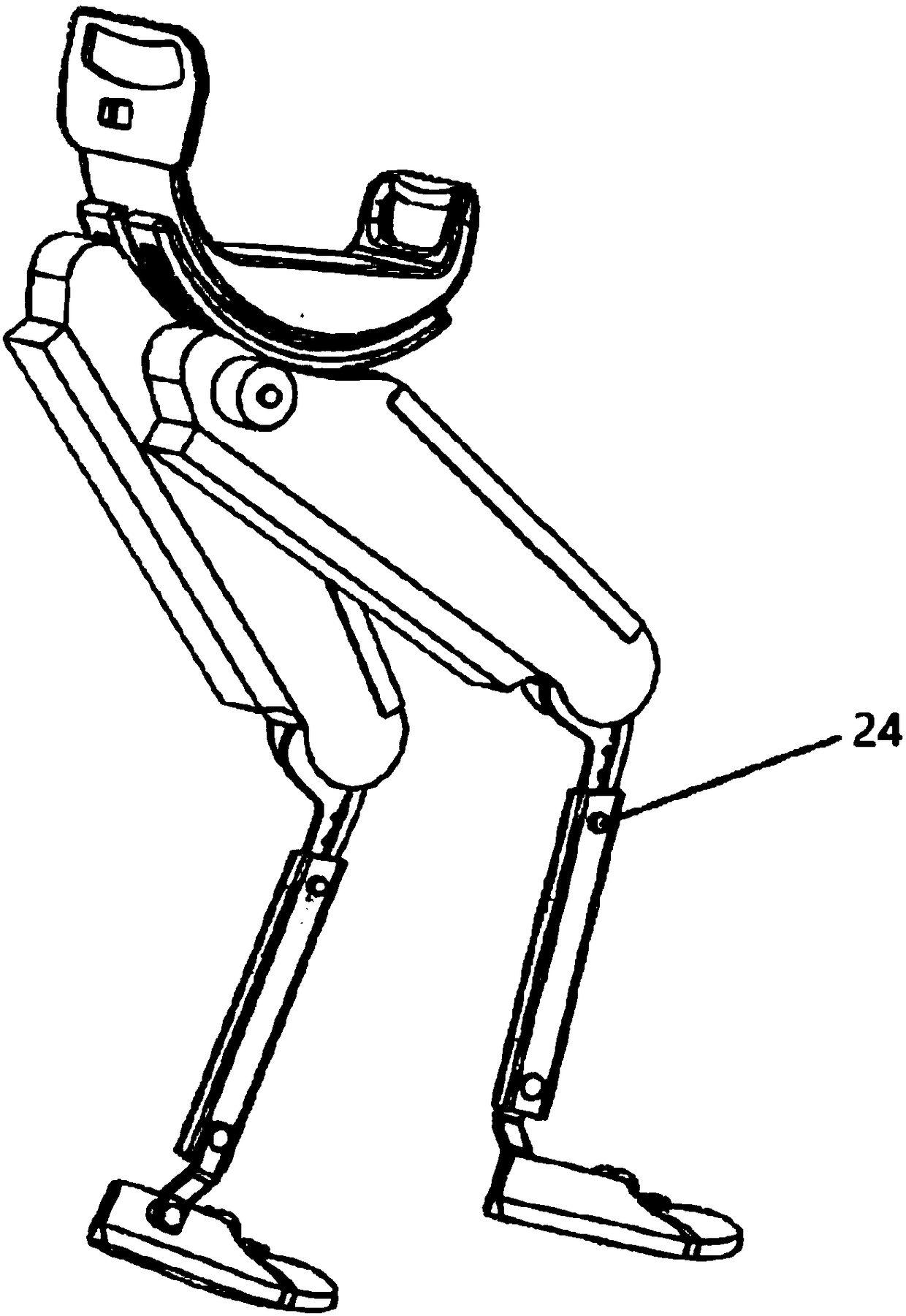
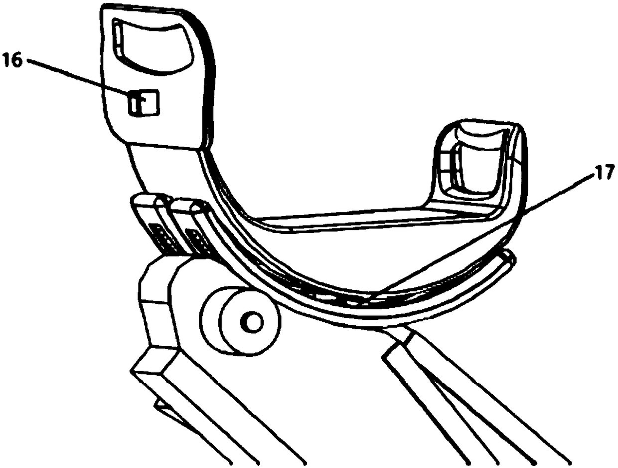
[0050] Such as figure 1 Shown: including seat cushion 1, track assembly 2, control device 3, thigh shell 4, calf assembly 5, calf shell 6, I-shaped connecting rod 7, rotating assembly 8, shoes 9, plantar force sensor 10, connecting frame 11, Teflon rope 12, battery 13, encoder 14, motor 15, gyroscope 16, spring set 17, pulley 18, gear 19, thigh link 20, Kvaser 21, driver 22, rotating shaft 23, knob handle 24, knee joint spring 25 , Slider 26. The track assembly 2 is connected to the lower end of the seat cushion 1 through the spring group 17, the upper end of the thigh link 20 is engaged with the track assembly 2 through the installation gear 19, and the pulley 18 is fixed on the track 2 through bolt connection, so that the thigh link 20 is relatively seat cushion 1 The rotation reduces the friction between the two. The thigh casing 4 is fixed on the thigh connecting rod 20 through bolt connection, and the battery 13 and the control device 3 are installed on the thigh casing...


PUM


Abstract

The invention discloses a wearable body weight support type walking aiding device. Through the addition of a chair and shoe part, the wearing and the fixation of the device are facilitated; meanwhile,through the structural design between the two legs, the space occupation can be reduced; the walking convenience can be realized; a motor is used for driving a gear; the bending and the extending ofa leg connecting rod are driven; a chair is further lifted so as to support the partial body weight; the burden of the leg muscle and joints during walking can be reduced; a Teflon rope and a spring device are arranged inside a calf connecting rod; the shinbone outwards extending assistance force during the walking is provided; the walking efficiency is improved; through the human body exercise and physical parameters obtained by a gyroscope and a foot sole force sensor, the exercise intention of the user is detected; the natural walking effect is achieved. In addition, the communication connection is built between an embedded control system and a mobile phone, so that the man-computer interaction and the real-time control on the robot can be better realized. The wearable body weight support type walking aiding device can be well applied to the wearable walking aiding device, can reduce the energy consumption during walking, can improve the comfort degree, and has great application values.

Description

technical field [0001] The invention relates to a lower extremity exoskeleton robot, in particular to a wearable body weight supporting walking assistance device. Background technique [0002] A wearable lower limb assisting robot is a human-machine integrated device that can assist people in various movements such as walking, sitting, squatting and standing. It can usually be realized by using manual equipment such as canes, crutches, and boosters. But the use of these manual instruments all depends on the strength of the arm. However, the strength of the arm is too small, the effect of weight loss is not obvious, and it is easy to fatigue the arm. In addition, when using these manual instruments, the arm cannot do other work because it is occupied, which will also bring many inconveniences in life. Patients with severe osteoarthritis often choose to go out in a wheelchair. However, it is difficult to use a wheelchair to pass through steps or uneven road conditions, and ...

Claims


Application Information

Patent Timeline
Patent Type & Authority Applications(China)
IPC IPC(8): B25J9/00
CPCB25J9/0006
Inventor 李智军徐崔超袁培江
Owner UNIV OF SCI & TECH OF CHINA
Why Eureka
Try Eureka