Integrated efficient turbine with air outlet constraint structure

A constrained structure, integrated technology, applied in mechanical equipment, engine components, machines/engines, etc., can solve problems such as failure to achieve optimal performance, large differences in resistance of post-processing systems, and improve turbine efficiency and airflow. Loss reduction and efficiency improvement effect

Inactive Publication Date: 2018-09-21
康跃科技(山东)有限公司
View PDF0 Cites 0 Cited by
  • Summary
  • Abstract
  • Description
  • Claims
  • Application Information

AI Technical Summary

Problems solved by technology

[0006] In order to match engines with different displacements and powers, a series of turbochargers must match multiple different turbines, especially for engines with emission levels of national 5, national 6 and non-road national 3 and national 4. The resistance of the processing system is quite different, and it is necessary to match turbines with different flow characteristics. When doing performance test matching, due to the cost of the mold, it is impossible to process too many turbine shells for fine matching, and the optimal performance cannot be achieved.

Method used


Image

  • Integrated efficient turbine with air outlet constraint structure
  • Integrated efficient turbine with air outlet constraint structure
  • Integrated efficient turbine with air outlet constraint structure

Examples


Embodiment 1

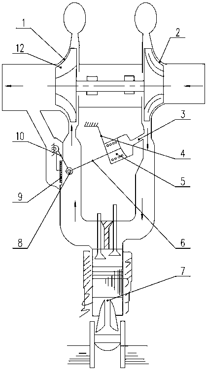
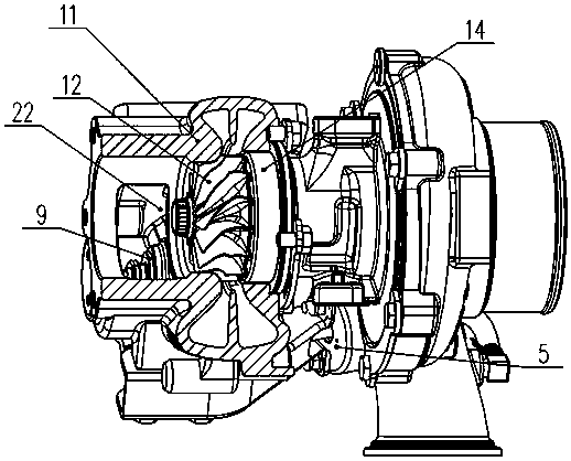
[0038] Such as Figure 4 , Figure 5 and Figure 6 Commonly shown, the integrated high-efficiency turbine with an air outlet restriction structure includes a turbine casing 11 and a turbine casing cover plate 16 installed at the end of the turbine casing 11. A turbine 12 and an air outlet guide groove 18 are installed in the turbine casing 11. The turbine casing 11 is provided with a turbine casing bypass exhaust passage 21 and a turbine exhaust gas passage 22 , and the turbine casing bypass exhaust passage 21 and the turbine exhaust gas passage 22 extend from the turbine casing 11 to the turbine casing cover plate 16 . The turbine casing bypass exhaust passage 21 and the turbine exhaust passage 22 guide the airflow separately, and the two do not directly communicate with each other. Both the turbine casing bypass exhaust passage 21 and the turbine exhaust passage 22 are tapered. The side wall of the turbine casing cover plate 18 is provided with a bypass guide hole 20 comm...

Embodiment 2

[0050] like Figure 7 and Figure 8 Commonly shown, the integrated high-efficiency turbine with an air outlet restriction structure includes a turbine casing 11 and a turbine casing cover plate 16 installed at the end of the turbine casing 11. A turbine 12 and an air outlet guide groove 18 are installed in the turbine casing 11. The turbine casing 11 is provided with a turbine casing bypass exhaust passage 21 and a turbine exhaust gas passage 22 , and the turbine casing bypass exhaust passage 21 and the turbine exhaust gas passage 22 extend from the turbine casing 11 to the turbine casing cover plate 16 . The turbine casing bypass exhaust passage 21 and the turbine exhaust passage 22 guide the airflow separately, and the two do not directly communicate with each other. Both the turbine casing bypass exhaust passage 21 and the turbine exhaust passage 22 are tapered. The side wall of the turbine casing cover plate 18 is provided with a bypass guide hole 20 communicating with t...

Embodiment 3

[0055] like Figure 9 and Figure 10 Commonly shown, the integrated high-efficiency turbine with an air outlet restriction structure includes a turbine casing 11 and a turbine casing cover plate 16 installed at the end of the turbine casing 11. A turbine 12 and an air outlet guide groove 18 are installed in the turbine casing 11. The turbine casing 11 is provided with a turbine casing bypass exhaust passage 21 and a turbine exhaust gas passage 22 , and the turbine casing bypass exhaust passage 21 and the turbine exhaust gas passage 22 extend from the turbine casing 11 to the turbine casing cover plate 16 . The turbine casing bypass exhaust passage 21 and the turbine exhaust passage 22 guide the airflow separately, and the two do not directly communicate with each other. Both the turbine casing bypass exhaust passage 21 and the turbine exhaust passage 22 are tapered. The side wall of the turbine casing cover plate 18 is provided with a bypass guide hole 20 communicating with ...


PUM


Abstract

The invention discloses an integrated efficient turbine with an air outlet constraint structure. The integrated efficient turbine comprises a turbine housing, wherein a turbine and an air outlet diversion trench are arranged in the turbine housing; the air outlet diversion trench is positioned at the air outlet end of the turbine housing, can increase the turbine rear pressure and improves the stability of turbine rear airflow; the initial end of the air outlet diversion trench is close to the turbine; the final end of the air outlet diversion trench extends towards the air outlet end of the turbine housing; and the external diameter of the air outlet diversion trench is gradually increased from the initial end to the tail end. The integrated efficient turbine has the advantages that the turbine front pressure is high, realization of EGR is facilitated, the turbine rear airflow is stable and the turbine is high in efficiency.

Description

technical field [0001] The invention relates to a turbine used for a turbocharger, in particular to an integrated high-efficiency turbine with an air outlet restriction structure, which can be applied to turbines with fixed cross-section and variable cross-section, and belongs to the technical field of internal combustion engines. Background technique [0002] The speed range of the vehicle engine is wide, and the turbocharger is limited by the characteristics of the engine and the supercharger, so it is difficult to obtain the best match at both high and low speed ends. If it is matched with the medium-high speed end, the boost pressure at the low-speed end is insufficient. In order not to deteriorate the smoke emission performance, the fuel supply has to be limited, thereby sacrificing the low-speed torque and affecting the low-speed drivability of the vehicle. The wastegate turbocharger is a product developed to solve the low-speed power shortage of the diesel engine. It ...

Claims


Application Information

Patent Timeline
Patent Type & Authority Applications(China)
IPC IPC(8): F01D9/00F01D25/24
CPCF01D9/00F01D25/24
Inventor 李延昭张金明李伟邵同林信效芬刘永芳
Owner 康跃科技(山东)有限公司
Why Eureka
Try Eureka