Radar calibration system and method

A technology of calibration system and calibration method, applied in the field of radar calibration system, to achieve the effect of improving accuracy

Inactive Publication Date: 2018-09-21
ANHUI JIANGHUAI AUTOMOBILE GRP CORP LTD
View PDF6 Cites 27 Cited by
  • Summary
  • Abstract
  • Description
  • Claims
  • Application Information

AI Technical Summary

Problems solved by technology

However, for the millimeter-wave radar mounted on the vehicle, there is a certain error between the actual installation angle and the designed installation angle. If the error exceeds a certain range, when the target moves in a straight line parallel to the longitudinal direction of the vehicle body, the target measured by the radar will move. There is a certain angle between the trajectory and the longitudinal direction of the vehicle body

Method used


Image

  • Radar calibration system and method
  • Radar calibration system and method
  • Radar calibration system and method

Examples


Embodiment Construction

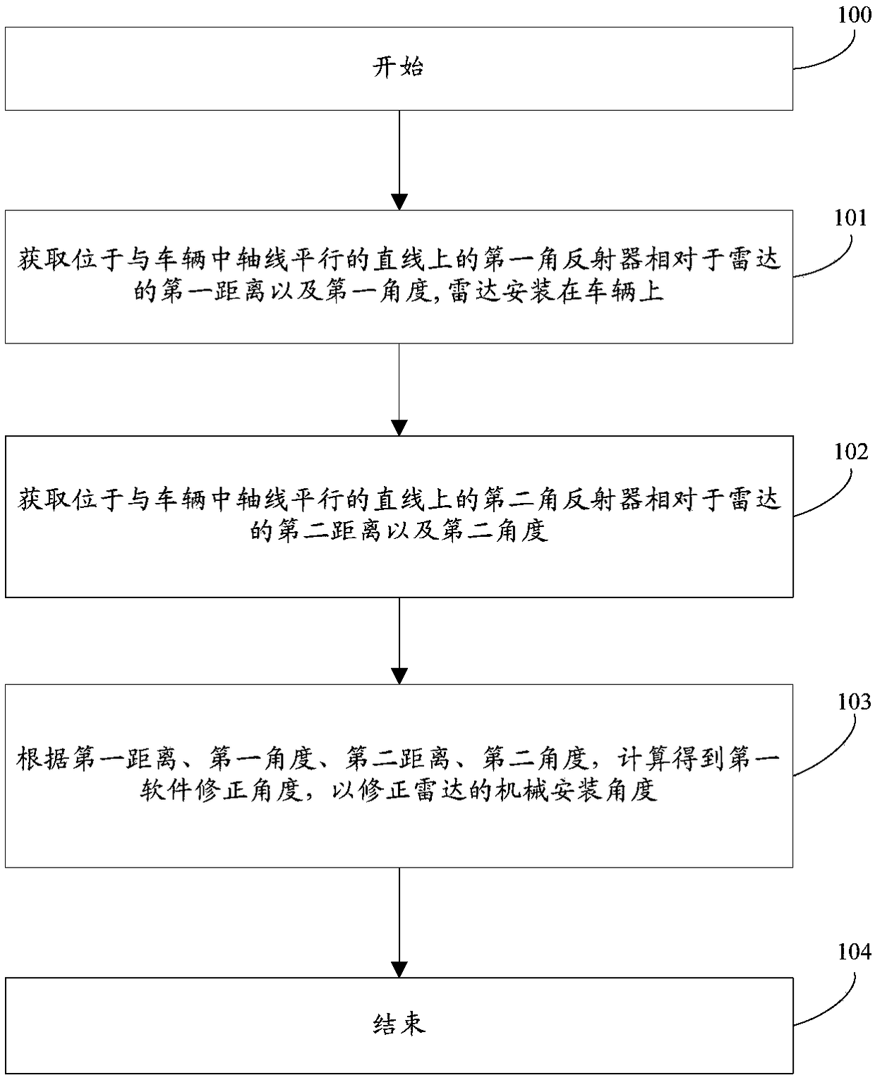
[0031] In order to enable those skilled in the art to further understand the features and technical contents of the present invention, the embodiments of the present invention will be described in detail below in conjunction with the accompanying drawings and implementation methods.

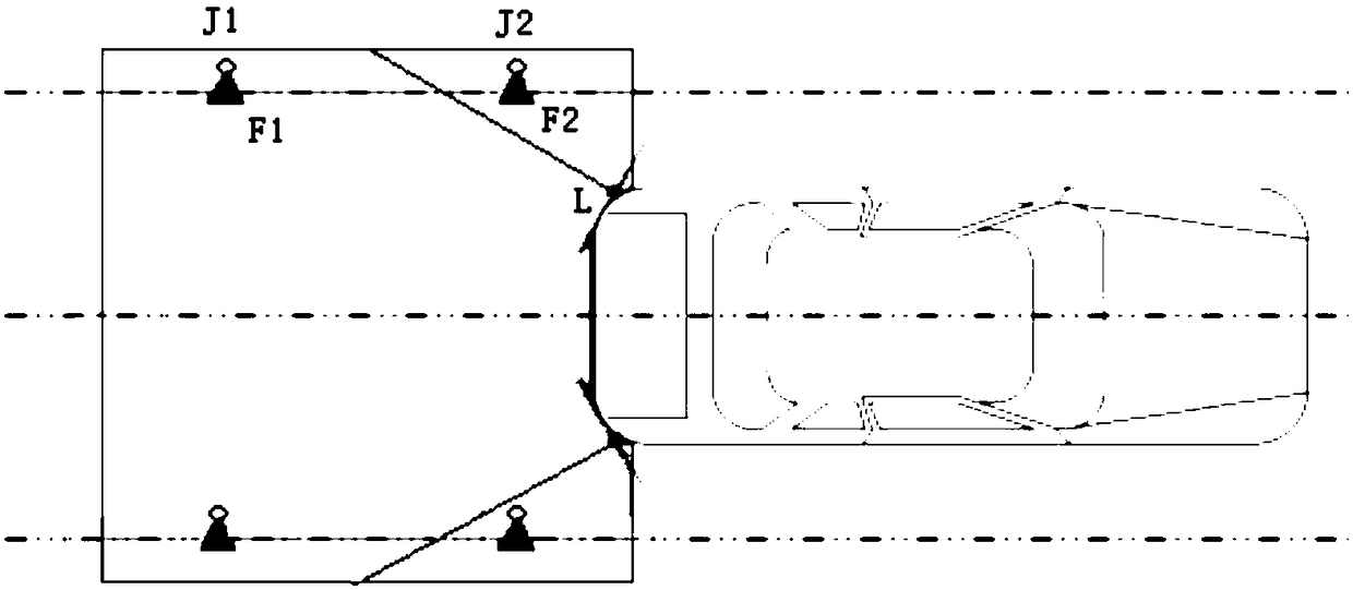
[0032] Such as figure 1 Shown is a schematic diagram of the structure of the radar calibration system according to the embodiment of the present invention, including: a vehicle located in the darkroom, the vehicle is equipped with a radar L and a radar controller (not shown) connected to the radar L, The system also includes: a first corner reflector F1 and a second corner reflector F2 respectively located on a straight line parallel to the central axis of the vehicle, and a first laser range finder is installed on the first corner reflector F1 J1, a second laser range finder J2 is installed on the second reflector F2, and the radar controller is respectively connected with the first laser range ...


PUM


Abstract

The invention relates to the field of vehicle-mounted radar application, in particular to a radar calibration system and method. The system comprises a vehicle located in a dark room, a radar and a radar controller connected to the radar are mounted on the vehicle, and the system further comprises first corner reflectors and second corner reflectors which are located on straight lines parallel toa central axis of the vehicle respectively; first laser range finders are mounted on the first corner reflectors, and second laser range finders are mounted on the second corner reflectors; the radarcontroller is used for acquiring a first distance, a first angle, a second distance and a second angle and conducting calculation according to the first distance, the first angle, the second distanceand the second angle for obtaining a first software correction angle to correct a mechanical mounting angle of the radar. By means of the radar calibration system and method, the calibration accuracyof the vehicle-mounted radar is improved.

Description

technical field [0001] The invention relates to the application field of vehicle radar, in particular to a radar calibration system and method. Background technique [0002] The blind spot monitoring system mainly uses microwaves to detect information such as the distance, azimuth and speed of the target vehicle or obstacle behind the vehicle, and uses this information to locate the target behind the opposite side; it can effectively overcome the situation at night or when visibility is poor (haze, rain, snow, dust, fog and other weather), detect potential dangerous targets in the blind area of ​​the vehicle and adjacent lanes, provide the driver with early warning before the accident, effectively prevent the occurrence of potential traffic accidents, and protect personnel and property to the greatest extent Safety. [0003] The blind spot monitoring system detects the vehicle information on the roads on both sides of the vehicle's exterior rearview mirror through two milli...

Claims


Application Information

Patent Timeline
Patent Type & Authority Applications(China)
IPC IPC(8): G01S7/40
CPCG01S7/40
Inventor 朱子甲何少斌汪进李卫兵刘江波李东浩束照坤
Owner ANHUI JIANGHUAI AUTOMOBILE GRP CORP LTD
Why Eureka
Try Eureka