
Disturbed Region Update Method for Steady Compressible Flow

A region update and dynamic technology, applied in the field of computational fluid dynamics, can solve problems such as numerical errors and flow parameters without actual beneficial contributions, and achieve the effect of reducing the total number of iteration steps, reducing the amount of solutions, and reducing storage requirements

Active Publication Date: 2021-01-12
BEIHANG UNIV
View PDF4 Cites 0 Cited by
  • Summary
  • Abstract
  • Description
  • Claims
  • Application Information

AI Technical Summary

Problems solved by technology

For undisturbed grid cells and grid cells whose solution has reached the convergence condition, the update of the flow parameters has no practical beneficial contribution to the solution of the entire flow field
[0007] 2) Introduce numerical error

Method used


Image

  • Disturbed Region Update Method for Steady Compressible Flow
  • Disturbed Region Update Method for Steady Compressible Flow
  • Disturbed Region Update Method for Steady Compressible Flow

Examples


Embodiment 1

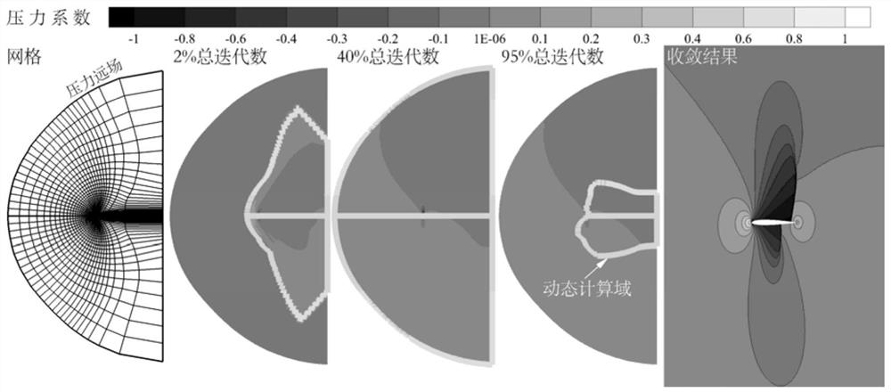
[0133] Example 1: The NACA 0012 airfoil is simulated under the conditions of incoming flow Mach number 0.85 and angle of attack 1°, and the flow field is initialized with far-field boundary conditions. The grid adopts C-type topology; in order to avoid the influence of the limited outer boundary on the results, the given computational domain is about 20 times the chord length. figure 2 The sparse mesh, dynamic computational domain changes, and final simulation results are illustrated. figure 2 In the convergence results shown, the shock waves on the upper and lower surfaces of the airfoil can be clearly captured. The relative error between the airfoil surface lift and drag coefficient obtained by the disturbance area updating method proposed by the invention and the result of the traditional global updating equation is less than 1 / 10,000.

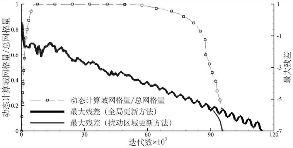
[0134] image 3 The variation of the grid cell size of the dynamic computational domain with iterations is given. The dynamic calcula...

Embodiment 2

[0136] Example 2: Simulate the flow around a cylinder with an incoming flow Mach number of 2.5, and the flow field is initialized with far-field boundary conditions. Figure 4 The dynamic computational domain change of sparse grid, explicit / implicit time format, and the numerical simulation comparison of the explicit / implicit time format perturbed region update method with the shock wave assembly method and the implicit global update method are presented. Figure 4 The comparison of the sub-figures on the right shows that the shock wave position and flow field characteristics of the flow field obtained by the disturbance area update method proposed by the present invention and other methods can be well matched; and whether it is explicit time advance or implicit time advance, The perturbed region update method can obtain numerical results with the same precision as the global update.

[0137] Figure 5 The variation of the grid cell size of the dynamic computational domain wi...


PUM


Abstract

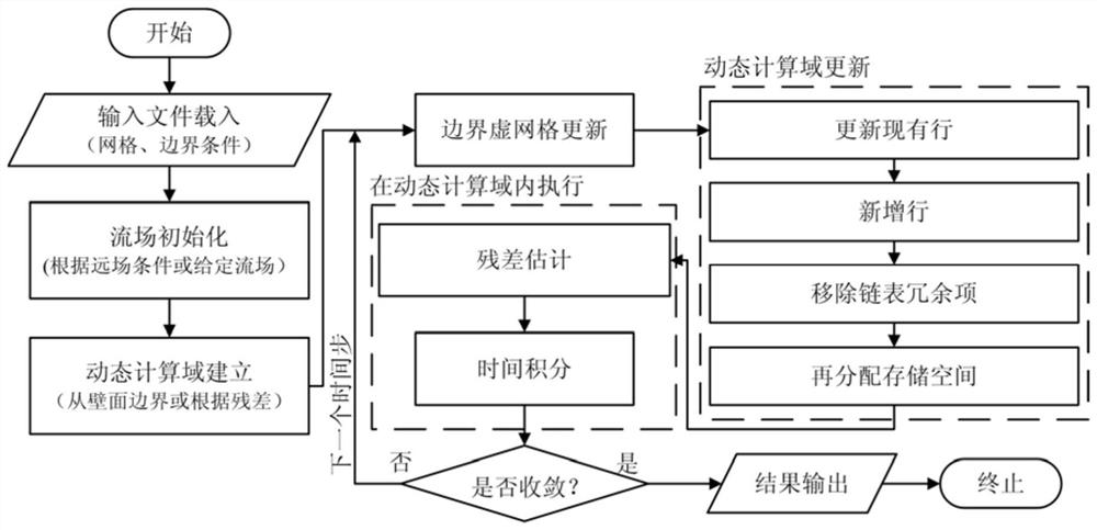
The invention discloses a disturbance region updating method of steady compressible flow, and belongs to the technical field of computational fluid mechanics. The method includes steps of input file loading, flow field initialization, dynamic-computation-domain establishment, boundary virtual-grid updating, dynamic-computation-domain updating, residual estimation, time integration, judgment of whether convergence occurs and result output. The method is suitable for use in solving of any compressible flow on the basis of a time-propulsion method, can be combined with any spatial discrete formatand time-propulsion format and other existing time-propulsion acceleration technology, and is suitable for use in different initialization methods and complex and discontinuous wall surface conditions. The method can greatly improve calculation efficiency; for the subsonic-speed flow problem, the method can reasonably remove redundant far-field units in a later stage of solving near a steady state, and effectively narrow a computational domain; and for the supersonic-speed flow problem, the method can also reduce a storage requirement of a solving process.

Description

technical field [0001] The invention belongs to the technical field of computational fluid dynamics, in particular to a method for updating a disturbed area of ​​a steady compressible flow, and to the principle and realization of a numerical simulation convergence rate acceleration technology. Background technique [0002] The mathematical properties of the Euler / N-S equations with time derivatives are always hyperbolic for both subsonic and supersonic flows. Therefore, the time-advancing method is generally used in current computational fluid dynamics to solve steady compressible flow problems. The time-advancing method starts with arbitrary conditions, integrates the unsteady governing equations along time, and takes the flow field obtained when the time approaches infinity as the flow field in a steady state. [0003] However, the solution of the flow field based on the time-advancing method is often extremely time-consuming, and efficient convergence acceleration technol...

Claims


Application Information

Patent Timeline
Patent Type & Authority Patents(China)
IPC IPC(8): G06F30/28G06F113/08G06F119/14
CPCG06F30/20
Inventor 蒋崇文胡姝瑶高振勋李椿萱
Owner BEIHANG UNIV
Learn More