Optimal debugging method for resistance of cooling water circulation system

A technology of circulation system and debugging method, which is applied in the field of pipeline system, can solve problems affecting normal production, unbalanced hydraulic distribution, system hydraulic imbalance, etc., and achieve the effect of online debugging

Active Publication Date: 2021-01-26
浙江科维节能技术股份有限公司
View PDF7 Cites 0 Cited by
  • Summary
  • Abstract
  • Description
  • Claims
  • Application Information

AI Technical Summary

Problems solved by technology

[0004] 1. Simply adjust the outlet of the water pump to correct the existing flow to the rated flow. If the existing flow is greater than the rated flow, but the system has serious hydraulic imbalance and multiple heat exchange bottlenecks, the corrected rated flow will often expose the heat exchange bottleneck. out, and adjusting the outlet of the water pump will reduce the system header pressure and total flow, affecting the normal use of the system;
[0005] 2. Adjust the flow rate based solely on the judgment of the temperature difference between the overall supply and return water (theoretically, under a certain system capacity, over-flow operation will lead to a small temperature difference). This can only achieve the purpose of energy saving in a system with excellent hydraulic balance. However, if the hydraulic distribution of the system is unbalanced, or the heat cannot be brought out due to serious fouling of the heat exchanger, it will lead to the phenomenon that the reduced flow will often expose the use effect of areas with poor hydraulic conditions or poor heat exchange conditions, which will affect Production proceeds normally;

Method used


Image

  • Optimal debugging method for resistance of cooling water circulation system
  • Optimal debugging method for resistance of cooling water circulation system
  • Optimal debugging method for resistance of cooling water circulation system

Examples


Embodiment Construction

[0067] The present invention will be further described below in conjunction with the accompanying drawings and specific embodiments, so that those skilled in the art can better understand the present invention and implement it, but the examples given are not intended to limit the present invention.

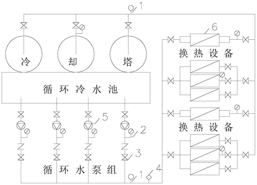
[0068] The cooling water circulation system resistance optimization debugging method of the present embodiment is characterized in that: comprising the following steps:

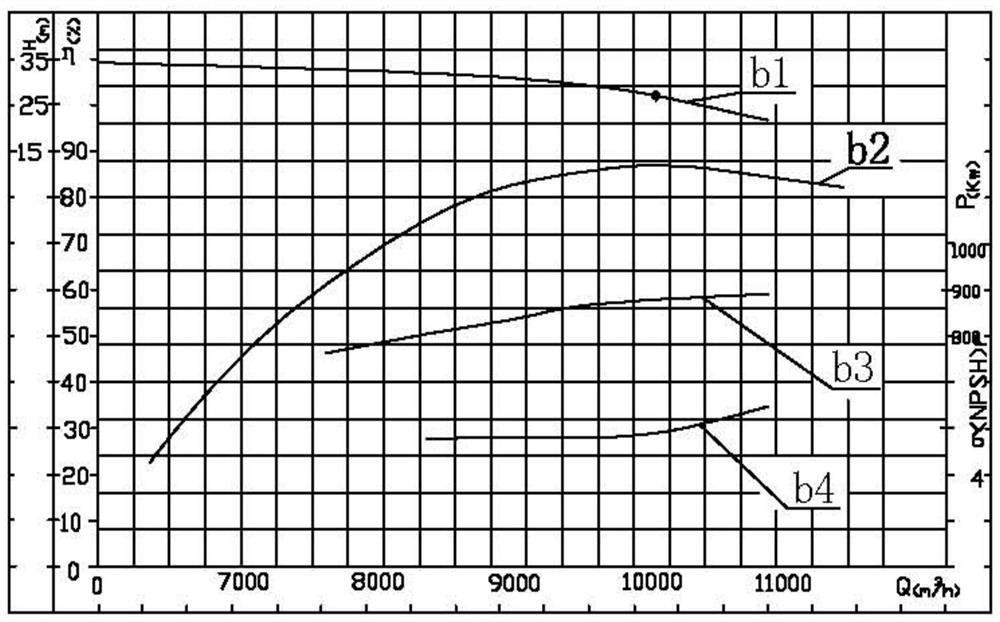
[0069] 1) Collect data: collect equipment parameters, system design operating parameters and system actual operating parameters of the circulating water system.

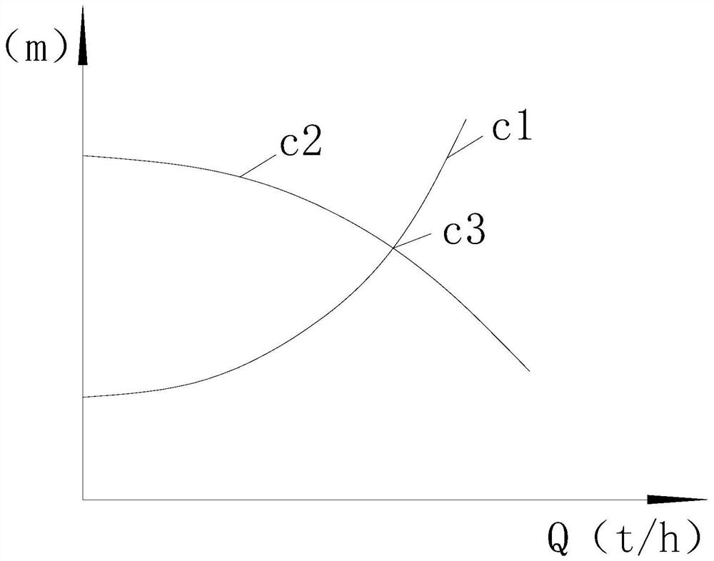
[0070] 2) Water supply flow analysis: calculate the actual temperature difference of the total supply and return water of the circulating water system, the actual temperature difference of the total supply and return water is the absolute value of the difference between the actual supply water temperature and the actual return water temperature of the ci...


PUM


Abstract

The invention discloses a method for optimizing and debugging the resistance of a cooling water circulation system, comprising the following steps: 1) collecting data; 2) analyzing the flow of water supply: if the difference between the design temperature difference of the total supply and return water and the actual temperature difference of the total supply and return water falls within If it is within the set threshold range, perform step 4); if the difference between the total supply and return water design temperature difference and the total supply and return water actual temperature difference falls outside the set threshold value range, adjust the operating flow rate of the circulating water system After the circulating water system runs stably under the operating flow conditions, perform step 3); 3) collect the actual operating parameters of the system again, and perform step 2) in a loop until the actual temperature difference of the total supply and return water falls below the set threshold 4) resistance analysis; 5) resistance concentration: concentrate all the abnormal resistance in the circulating water system on the outlet valve of the water pump, and calculate the optimal water supply capacity required by the circulating water system; 6) debugging: adjust the circulating water system from The current water supply capacity is adjusted to optimize the water supply capacity.

Description

technical field [0001] The invention belongs to the technical field of pipeline systems, in particular to a method for optimizing and debugging the resistance of a cooling water circulation system. Background technique [0002] As an important supporting system, the cooling circulating water system is used in various fields of national economic production including iron and steel, petrochemical, thermal power, etc. At present, it is basically in extensive operation, and its energy waste is very serious. At present, there is no intuitive, convenient, and easy-to-operate method for debugging in the transformation of circulating water systems. It cannot intuitively judge the loss of water pump resistance, cannot concentrate the resistance in the system to the outlet valve of the water pump, and cannot adjust the water pump in time according to the resistance ( impeller treatment or replacement of high-efficiency equipment that matches the system), will lead to the current serio...

Claims


Application Information

Patent Timeline
Patent Type & Authority Patents(China)
IPC IPC(8): G06Q10/04G06Q50/06E03B1/02
CPCE03B1/02G06Q10/04G06Q50/06
Inventor 杨永利林永辉吕伟未凯周飞万文杰刘冬平黄高岭万艳林
Owner 浙江科维节能技术股份有限公司
Why Eureka
Try Eureka