
Automatic washing machine of vibrating motor rotor assemblies

An automatic cleaning machine and vibration motor technology, applied in the manufacture of stator/rotor body, cleaning method using gas flow, cleaning method and utensils, etc., can solve the problems of slow speed, low efficiency, poor effect, etc., to prevent displacement. Effect

Pending Publication Date: 2018-09-21
阜南县特立电子有限公司
View PDF0 Cites 2 Cited by
  • Summary
  • Abstract
  • Description
  • Claims
  • Application Information

AI Technical Summary

Problems solved by technology

[0004] In order to solve the above technical problems, the present invention provides an automatic cleaning machine for vibration motor rotor assembly to solve the problems of manual cleaning of the existing motor rotor, slow speed, low efficiency and poor effect

Method used


Image

  • Automatic washing machine of vibrating motor rotor assemblies
  • Automatic washing machine of vibrating motor rotor assemblies

Examples


Embodiment

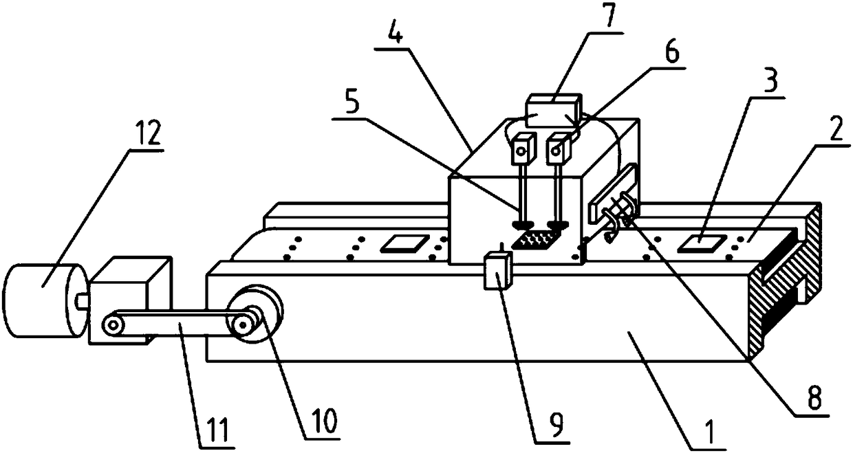
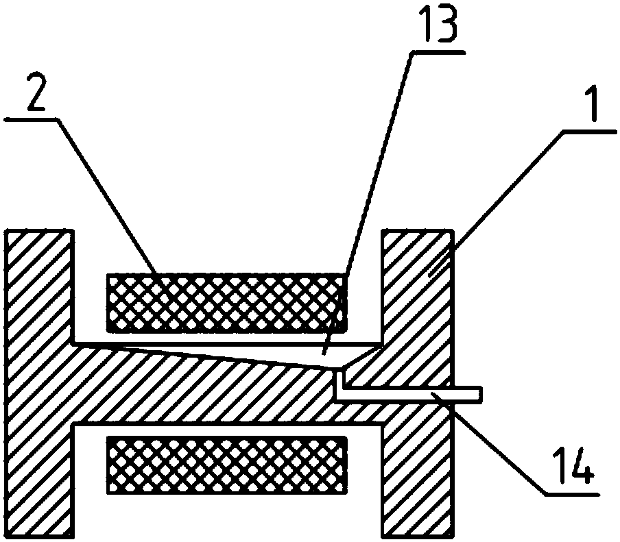
[0019] as attached figure 1 to attach figure 2 shown

[0020] The present invention provides an automatic cleaning machine for a vibration motor rotor assembly, including a positioning guide rail 1, a conveyor belt 2, an adsorption sticker 3, a transparent cover body 4, a cleaning blowing device 5, a pressure regulating valve 6, a delay relay 7, and a drying device 8 , optical fiber sensor 9, pulley 10, conveyor belt 11, motor 12, water collecting tank 13 and leaking pipe 14, described positioning guide rail 1 is set as " I " font support guide rail, and is provided with pulley 10 rotations by its two ends Connected with a conveyor belt 2, the upper part of the conveyor belt 2 is equidistantly provided with adsorption stickers 3 for fixing the rotor jig; the middle part of the upper end of the positioning guide rail 1 is provided with a transparent cover 4, and the inner cavity of the transparent cover 4 Vertically be provided with cleaning air blowing device 5, the upper e...


PUM


Abstract

The invention provides an automatic washing machine of vibrating motor rotor assemblies. The automatic washing machine comprises a positioning guide rail, a conveyer belt, adsorbing stickers, a transparent hood body, washing and blowing devices, pressure regulating valves, a delay relay, a drying device, an optical fiber sensor, a belt wheel, a transmission belt, a motor, a water collecting tank and a water leaking pipe, wherein the positioning guide rail is an I-shaped supporting guide rail. According to the automatic washing machine disclosed by the invention, the washing and blowing devices, the delay relay and the optical fiber sensor are arranged, so that when the optical fiber sensor senses that products are in the right place, the delay relay drives the washing and blowing devices to automatically wash the products after receiving a command, and when the washing and blowing devices stop washing, the automatic washing of the rotor assemblies is completed. Due to adoption of the automatic washing machine disclosed by the invention, the operating type of automatic washing of the rotor assemblies is realized, so that staff is saved, and the production efficiency is improved by 60 times, the phenomena that during manual washing, the operating speed is low, the efficiency is low, and when the products are placed in the right place, foreign matters in an inner hole of a bearingcannot be accurately washed out are avoided, the quality of the products is improved, and the production efficiency is improved.

Description

technical field [0001] The invention belongs to the technical field of mechanical automation, and in particular relates to an automatic cleaning machine for a vibration motor rotor assembly. Background technique [0002] Vibration motor rotor assembly, currently adopts manual cleaning process. The operator manually picks up the rotor assembly to clean the operation method. When cleaning manually, the operation speed is slow and the efficiency is low. [0003] Therefore, it is very necessary to invent a kind of vibration motor rotor assembly automatic cleaning machine. Contents of the invention [0004] In order to solve the above technical problems, the present invention provides an automatic cleaning machine for vibration motor rotor assembly to solve the problems of slow speed, low efficiency and poor effect of manual cleaning of the existing motor rotor. An automatic cleaning machine for vibration motor rotor components, including positioning guide rails, conveyor bel...

Claims


Application Information

Patent Timeline
IPC IPC(8): H02K15/02B08B5/02
CPCH02K15/02B08B5/02
Inventor 李伟德王丹刘崇根王和平
Owner 阜南县特立电子有限公司
Learn More