Cryogenic residual liquid treatment device
A technology for processing device and residual liquid, applied in evaporator accessories, evaporation, chemical instruments and methods, etc., can solve the safety hazards of operators and the environment, freeze the civil foundation of residual liquid pit, and generate a large amount of concentrated liquid in the area around the residual liquid pit. fog and other problems, to achieve the effect of no maintenance, uniform flow velocity distribution, and increased spreading area
- Summary
- Abstract
- Description
- Claims
- Application Information
AI Technical Summary
Problems solved by technology
Method used
Image
Examples
Embodiment 1
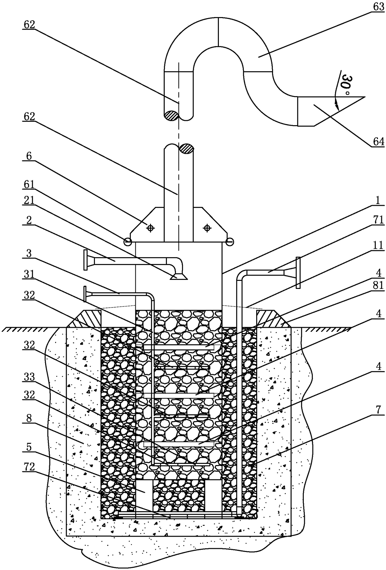
[0020] The low-temperature raffinate treatment device of embodiment 1, such as figure 1 As shown, it includes a cylinder 1 with an upper opening, a liquid inlet pipe 2 and a heating pipe 3. The cylinder 1 is made of stainless steel. The lower part of the cylinder 1 is buried below the ground of the concrete foundation 8, and the top of the cylinder 1 is equipped with a cover An exhaust pipe 62 is installed on the plate 6 and the cover plate 6, the upper end of the exhaust pipe 62 communicates with the outside atmosphere, the lower end of the exhaust pipe 62 communicates with the cylinder body 1, and the outlet of the liquid inlet pipe 2 passes through the side of the cylinder body 1 The wall enters the cylinder body 1, the outlet of the liquid inlet pipe 2 faces downward, and a nozzle 21 is installed at the outlet of the liquid inlet pipe 2, and the inlet of the liquid inlet pipe 2 is discharged from the low-temperature residual liquid of the air separation unit (not shown in t...
Embodiment 2
[0021] The low-temperature raffinate treatment device of embodiment 2, such as figure 1 As shown, it includes a cylinder 1 with an upper opening, a liquid inlet pipe 2 and a heating pipe 3. The cylinder 1 is made of stainless steel. The lower part of the cylinder 1 is buried below the ground of the concrete foundation 8, and the top of the cylinder 1 is equipped with a cover An exhaust pipe 62 is installed on the plate 6 and the cover plate 6, the upper end of the exhaust pipe 62 communicates with the outside atmosphere, the lower end of the exhaust pipe 62 communicates with the cylinder body 1, and the outlet of the liquid inlet pipe 2 passes through the side of the cylinder body 1 The wall enters the cylinder body 1, the outlet of the liquid inlet pipe 2 faces downward, and a nozzle 21 is installed at the outlet of the liquid inlet pipe 2, and the inlet of the liquid inlet pipe 2 is discharged from the low-temperature residual liquid of the air separation unit (not shown in t...
Embodiment 3
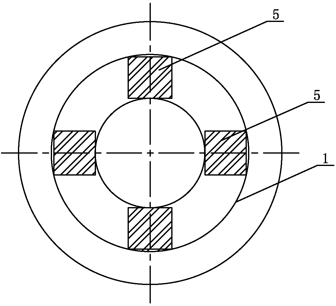
[0022] The low-temperature raffinate treatment device of embodiment 3, such as figure 1 As shown, it includes a cylinder 1 with an upper opening, a liquid inlet pipe 2 and a heating pipe 3. The cylinder 1 is made of stainless steel. Three angle steel rings 4 are arranged on the inside of the cylinder 1, and the three angle steel rings 4 are arranged along the cylinder 1. The inner wall is arranged up and down, the lower part of the cylinder body 1 is buried below the ground of the concrete foundation 8, the top of the cylinder body 1 is equipped with a cover plate 6, the cover plate 6 is conical, and the flange ring is passed between the cover plate 6 and the cylinder body 1 61 is fixed, and an exhaust pipe 62 is installed on the cover plate 6. The upper end of the exhaust pipe 62 communicates with the outside atmosphere. The upper end of the exhaust pipe 62 is provided with an elbow 63, which is close to the outlet of the exhaust pipe 62, and the exhaust The outlet of the pip...
PUM
 Abstract
Description
Claims
Application Information
 - R&D
- Intellectual Property
- Life Sciences
- Materials
- Tech Scout
- Unparalleled Data Quality
- Higher Quality Content
- 60% Fewer Hallucinations
Browse by: Latest US Patents, China's latest patents, Technical Efficacy Thesaurus, Application Domain, Technology Topic, Popular Technical Reports.
© 2025 PatSnap. All rights reserved.Legal|Privacy policy|Modern Slavery Act Transparency Statement|Sitemap|About US| Contact US: help@patsnap.com


