Self-rotation angle tool

A self-rotating and tooling technology, applied in positioning devices, manufacturing tools, metal processing equipment, etc., can solve the problems of high cost and difficult angle adjustment, and achieve the effect of simple structure, simple and convenient operation process, and material cost saving.

Inactive Publication Date: 2018-09-25
CHANGZHOU XINGYU AUTOMOTIVE LIGHTING SYST
View PDF6 Cites 2 Cited by
  • Summary
  • Abstract
  • Description
  • Claims
  • Application Information

AI Technical Summary

Problems solved by technology

[0004] In order to solve the defects of difficult angle adjustment and high cost in the prior art, the present invention provides an easy-to-adjust, low-cost self-rotation angle tooling

Method used


Image

  • Self-rotation angle tool
  • Self-rotation angle tool
  • Self-rotation angle tool

Examples


Embodiment Construction

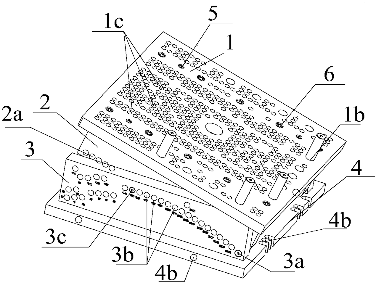
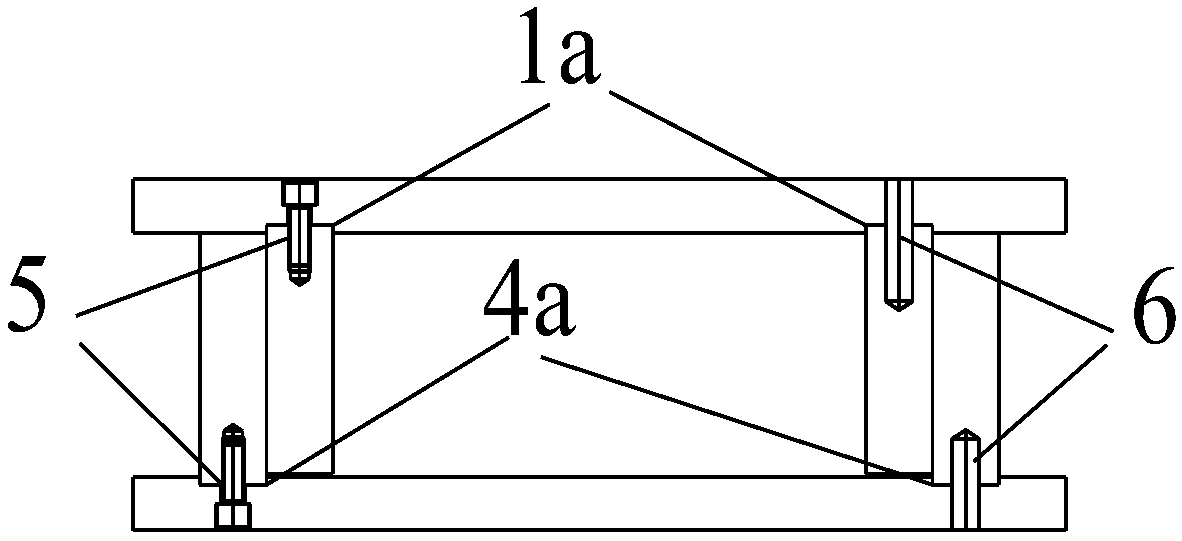
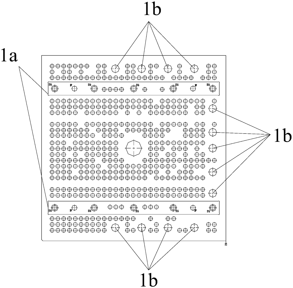
[0027] like Figure 1-6 , a self-rotating angle tooling, comprising an upper tooling assembly and a lower tooling assembly, the upper tooling assembly includes a bearing panel 1 for clamping workpieces, the lower tooling assembly is fixed along the horizontal direction, and the end of the upper tooling assembly is hinged to the lower tooling assembly , the lower tooling assembly is provided with several angle pin holes 3b, and the upper tooling assembly is provided with equidistant pin holes 2a aligned with one of the angle pin holes 3b when the bearing panel 1 rotates to a certain angle, and the angle pin holes 3b and A positioning piece is provided between the equidistant pin holes 2a to fix the relative positions of the upper tooling assembly and the lower tooling assembly. In this embodiment, the positioning member is the fixing pin 3c passing through the equidistant pin holes 2a and the angle pin holes 3b at the same time, and positioning blocks can also be used for posit...


PUM


Abstract

The invention relates to the technical field of die machining assistance tools, in particular to a self-rotation angle tool which comprises an upper tool assembly and a lower tool assembly. The uppertool assembly comprises a bearing face plate for clamping a workpiece, the lower tool assembly is fixed in the horizontal direction, the end of the upper tool assembly is hinged to the lower tool assembly, the lower tool assembly is provided with a plurality of angle pin holes, the upper tool assembly is provided with an equally-spaced pin hole aligned to one angle pin hole when the bearing face plate rotates at a certain angle, and positioning parts for fixing relative positions of the upper tool assembly and the lower tool assembly are arranged between the angle pin holes and the equally-spaced pin holes. The self-rotation angle tool is simple in structure, good in practicability and capable of saving cost and can rotate itself from 0 degree to 30 degrees.

Description

technical field [0001] The invention relates to the technical field of mold processing auxiliary tooling, in particular to a self-rotating angle tooling. Background technique [0002] In the field of mold processing, tooling fixture is a very common and effective auxiliary processing tool. Designing a clever and practical auxiliary tooling can make the original complex processing simple and controllable. The processing of parts with variable angles, inclined holes, and double inclined hole waterways brings processing difficulties to the processing of ordinary three-axis machine tools, low processing efficiency, and difficult control of processing accuracy. Under normal circumstances, corresponding angle tooling will be made according to the angle of the workpiece to be processed. For multiple angles of a workpiece, it is often necessary to make several or more tooling, resulting in increased manufacturing costs, longer production cycles, and low production efficiency. [00...

Claims


Application Information

Patent Timeline
Patent Type & Authority Applications(China)
IPC IPC(8): B23Q3/04
CPCB23Q3/04
Inventor 董浩
Owner CHANGZHOU XINGYU AUTOMOTIVE LIGHTING SYST
Why Eureka
Try Eureka