A vehicle braking simulation system

A simulation system and automobile braking technology, applied in the field of automobiles, can solve the problems such as the inability to adjust pedal feel and the inability of automatic systems to realize active braking, and achieve the effect of simple structure and good compatibility.

Active Publication Date: 2020-05-29
ZHEJIANG LEAPMOTOR TECH CO LTD
View PDF4 Cites 0 Cited by
  • Summary
  • Abstract
  • Description
  • Claims
  • Application Information

AI Technical Summary

Problems solved by technology

[0003] The present invention mainly solves the problems that the automatic system in the prior art cannot realize active braking and cannot adjust the pedal feeling, and provides an automobile braking simulation system

Method used


Image

  • A vehicle braking simulation system
  • A vehicle braking simulation system

Examples


Embodiment

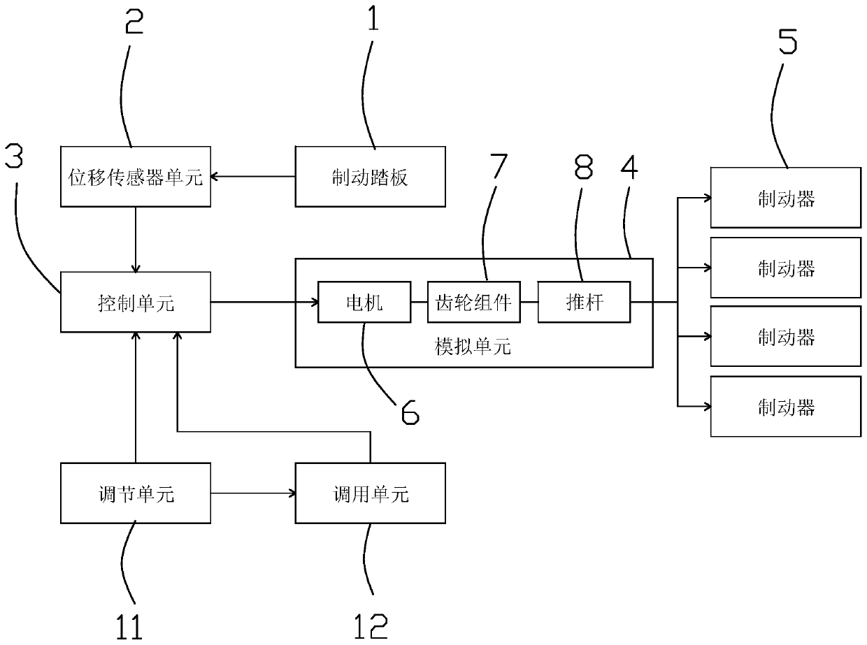
[0021] In this embodiment, a vehicle braking simulation system, such as figure 1 As shown, it includes a brake pedal 1, a number of brakes 5, a displacement sensor unit 2, a control unit 3, an analog unit 4, and an adjustment unit 11. The displacement sensor unit is arranged on the brake pedal, and the displacement sensor unit is connected with the control unit. The control unit It is connected with the analog unit, the analog unit is connected with each brake control, and the adjustment unit is connected with the control unit; wherein, the sensor unit is connected with the CAN bus of the vehicle, and the input terminal of the control unit is connected with the CAN bus. The control unit adopts the vehicle controller.

[0022] Sensor unit: used to monitor the displacement of the brake pedal;

[0023] Control unit: according to the displacement information of the brake pedal, output the corresponding voltage signal to control the operation of the motor;

[0024] Analog unit: i...


PUM


Abstract

The invention relates to an automobile brake simulation system. The system solves the problem in the prior art that an automatic system cannot achieve active braking and the pedal feeling cannot be adjusted. The system comprises a brake pedal and a plurality of brakes and further comprises a displacement sensor unit, a control unit, a simulation unit and an adjustment unit. The displacement sensorunit is disposed on the brake pedal and connected to the control unit, the control unit is connected to the simulation unit connected to the brakes in a control mode, and the adjustment unit is connected to the control unit. The system adopts the motor output torque to control operation of the brakes according to brake pedal displacement, and achieves the purpose of active braking of an automobile. A traditional vacuum servo system is not required, and the system is simpler in structure. The motor output torque can be adjusted through the adjustment unit to achieve adjustment of the brake pedal, and the problem that the pedal feeling of the traditional brake system is achieved by adjusting hardware parameters and cannot be changed once determined is solved.

Description

technical field [0001] The invention relates to the technical field of automobiles, in particular to an automobile braking simulation system. Background technique [0002] In the traditional braking system, the realization of braking is through the driver applying force on the brake pedal, which is amplified and converted into hydraulic pressure by the vacuum booster system, and acts on the brake to achieve braking. Now it is used in automobiles. The vacuum booster system consists of a vacuum booster with a brake master cylinder, a vacuum tank, a vacuum pump, and a vacuum tube. The vacuum booster with a brake master cylinder utilizes the pressure difference between the vacuum and the atmosphere to apply the braking force applied by the driver to the pedals. Amplify and transmit this force to the brake master cylinder to establish hydraulic pressure, realize the conversion of pedal force to hydraulic pressure, and then achieve braking. Among them, the vacuum tank is responsi...

Claims


Application Information

Patent Timeline
Patent Type & Authority Patents(China)
IPC IPC(8): B60T8/40B60L7/00
CPCB60L7/00B60T8/409
Inventor 宋建勋马涛锋
Owner ZHEJIANG LEAPMOTOR TECH CO LTD
Why Eureka
Try Eureka