Deep land-filling area gravity type retaining wall and reinforced soil retaining wall combined supporting structure

A support structure and gravity technology, applied in the field of geotechnical engineering, can solve the problems of low support height, high cost, large amount of engineering, etc., and achieve the effects of convenient construction, good environmental and economic benefits, and low cost.

Pending Publication Date: 2018-09-25
NORTHWEST ELECTRIC POWER DESIGN INST OF CHINA POWER ENG CONSULTING GROUP
View PDF7 Cites 2 Cited by
  • Summary
  • Abstract
  • Description
  • Claims
  • Application Information

AI Technical Summary

Problems solved by technology

The height of the retaining wall is not high when the retaining wall is used, and when the retaining height reaches a certain height, the bearing capacity is required to be high. Therefore, the retaining wall is generally used as the toe wall at the slope foot; The height of the cantilever section of the cantilever anti-slide pile should not exceed 15m. If the anchor cable anti-slide pile structure is considered, there will be a problem that the distance between the bedrock and the pile top is too large, which will cause the anchorage depth to be too large. Large quantity and high cost; For anchoring projects, the filling area is thick and the bedrock is deeply buried, so the anchoring effect is limited

Method used


Image

  • Deep land-filling area gravity type retaining wall and reinforced soil retaining wall combined supporting structure
  • Deep land-filling area gravity type retaining wall and reinforced soil retaining wall combined supporting structure

Examples


Embodiment

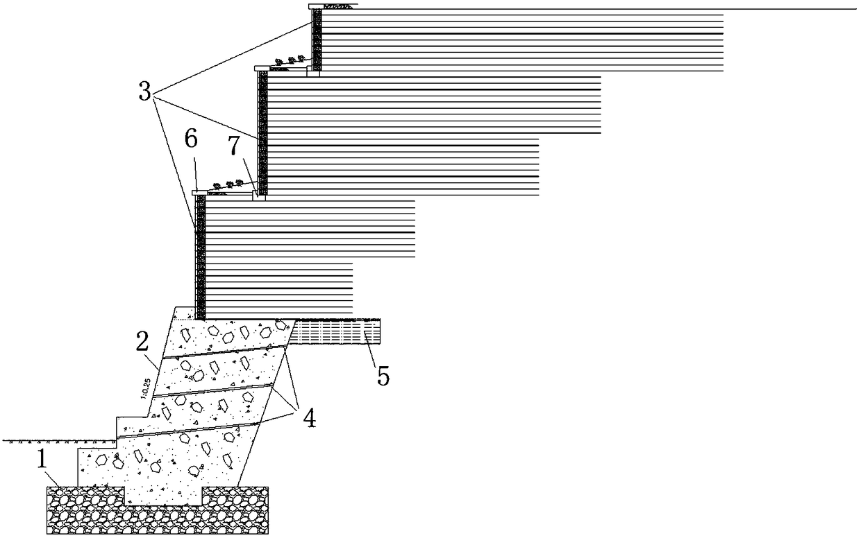
[0034] Such as figure 1 with figure 2 As shown, the backfill thickness of a certain project fill slope is 28m, the top of the slope is arranged with buildings, the foot of the slope is a natural gully with perennial water flow, the stratum is silty clay, and the characteristic value of the bearing capacity of the foundation is 290kPa.

[0035] The thickness of sand and gravel cushion layer 1 foundation treatment is 3m, and the width is 14.3m. The choice of sand and gravel materials should achieve reasonable gradation, and the content of fine grains should be controlled at 25% to 35%. The thickness of the single layer of sand and gravel cushion is 40cm, and the water content is controlled between 3% and 6%. During the construction, the surface is flattened by flat rolling once, and then vibrating and rolled six times. Compaction coefficient ≥ 0.97, foundation bearing capacity ≥ 450kPa.

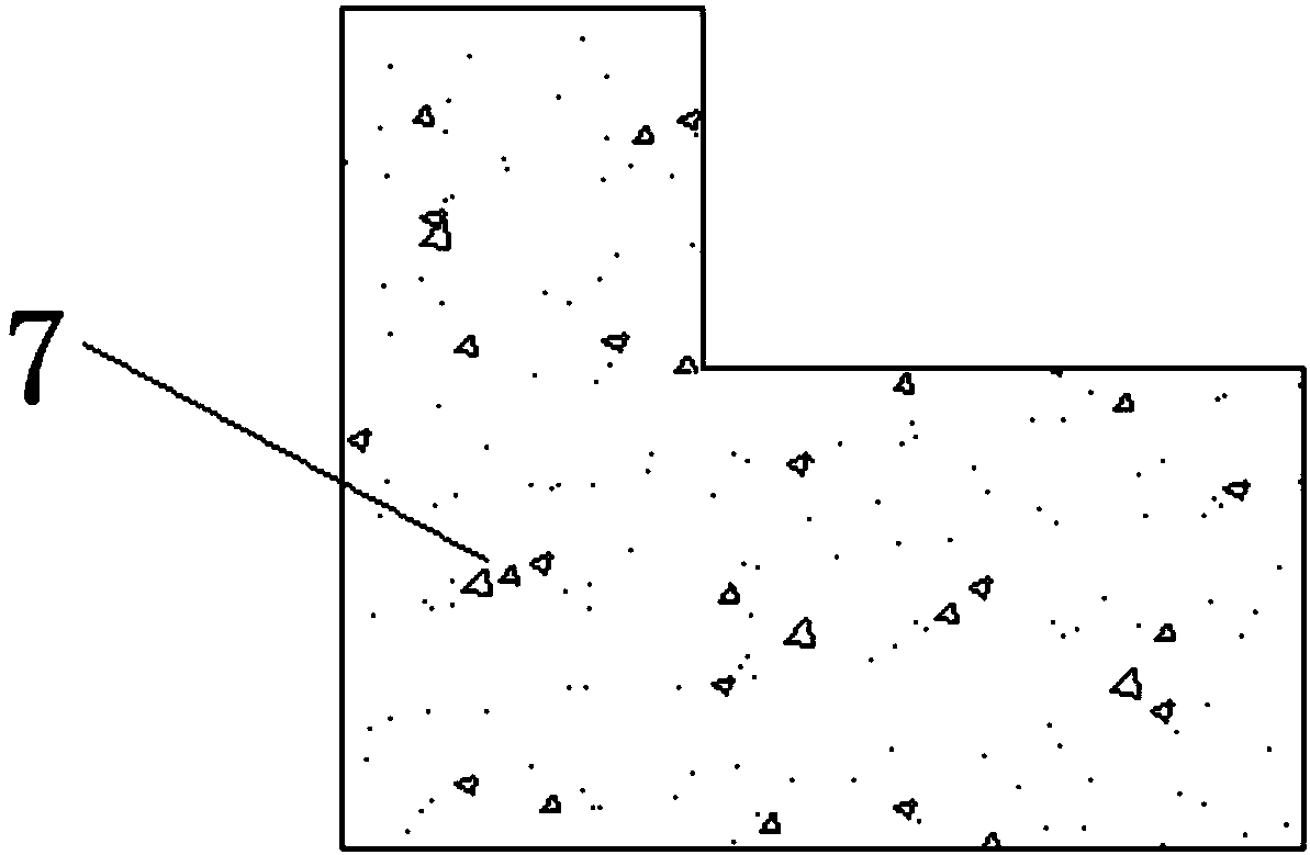
[0036] Gravity retaining wall 2 is a 10.8m-high rubble concrete retaining wall, includi...


PUM


Abstract

The invention discloses a deep land-filling area gravity type retaining wall and reinforced soil retaining wall combined supporting structure. The deep land-filling area gravity type retaining wall and reinforced soil retaining wall combined supporting structure comprises a sand gravel cushion layer, a gravity type soil retaining wall and a reinforced soil retaining wall, wherein the sand gravel cushion layer is arranged under the ground; the gravity type soil retaining wall is arranged on the sand gravel cushion layer; the reinforced soil retaining wall is arranged on the gravity type soil retaining wall which is of a multi-stage step structure; a wide platform is arranged between the reinforced soil retaining wall units of two stages; a base is arranged on the wide platform; the reinforced soil retaining wall unit at the upper stage is arranged on the top base of the reinforced soil retaining wall unit at the lower stage; the reinforced soil retaining wall unit at the lowest stage isarranged on the top of the gravity type soil retaining wall; and the inner side of the reinforced soil retaining wall is backfilled with soil. The deep land-filling area gravity type retaining wall and reinforced soil retaining wall combined supporting structure is convenient in construction, is low in manufacturing cost, and can obtain very good engineering benefits, environmental benefits and economical benefits.

Description

technical field [0001] The invention belongs to the technical field of geotechnical engineering, and relates to the engineering design of slope treatment, in particular to a combined support structure of a gravity type and a reinforced earth retaining wall in a deep and thick filling area. Background technique [0002] With the tense situation of land use in the country, more and more power plants and substations and other power engineering projects choose to build in mountainous areas with large terrain elevation differences. Due to the needs of leveling and layout of the project site, the high excavation slope and the fill slope formed by deep filling must be treated and designed to achieve the goals of safety, applicability, economical rationality and beautification of the environment. [0003] For large-area and large-thickness filling projects in mountainous areas, the rolling effect of backfill soil is often poor, the uniformity is poor, the overall strength is low, an...

Claims


Application Information

Patent Timeline
Patent Type & Authority Applications(China)
IPC IPC(8): E02D17/20E02D29/02
CPCE02D17/20E02D29/02
Inventor 刘志伟鄢治华杨生彬程东幸胡昕郭葆
Owner NORTHWEST ELECTRIC POWER DESIGN INST OF CHINA POWER ENG CONSULTING GROUP
Why Eureka
Try Eureka