Buoyant box type water floating gantry crane pipeline sinking construction method

A construction method, the technology of the door crane method, applied in the direction of pipeline laying and maintenance, pipes/pipe joints/fittings, mechanical equipment, etc., can solve the problems of uneven stress on local sections of pipelines, water surface drift and deformation, and high cost, etc., to achieve The construction principle is simple and easy, the repair operation is simple, and the effect of reducing the number of occupations

Active Publication Date: 2018-09-25
CHINA FIRST METALLURGICAL GROUP
View PDF7 Cites 14 Cited by
  • Summary
  • Abstract
  • Description
  • Claims
  • Application Information

AI Technical Summary

Problems solved by technology

[0003] (1) The overall pipeline is often used for launching, and some large-scale lifting cranes need to be arranged along the entire length of the pipeline for lifting, which is expensive and poses a great safety hazard during lifting
[0004] (2) Due to hoisting restrictions, long-distance pipelines cannot be welded as a whole on the shore, so the strength (hydraulic pressure) test for pipelines can only be carried out on the water surface, and it is difficult to inspect welds by traditional lifting
[0005] (3) When the pipeline sinks with water, it is easy to produce water flushing phenomenon, resulting in uneven stress on some sections of the pipeline and deformation. When construction is carried out by hoisting, it is very difficult to cooperate with each other due to the lifting of multiple cranes
[0006] (4) If only buoy boxes and gondolas are used for sinking, since they are all fixed by the mooring rope on the shore, when encountering wind and waves with a high flow rate, the water surface will easily drift and deform, resulting in inaccurate sinking of the steel pipe. sinking into an underwater trench

Method used


Image

  • Buoyant box type water floating gantry crane pipeline sinking construction method
  • Buoyant box type water floating gantry crane pipeline sinking construction method
  • Buoyant box type water floating gantry crane pipeline sinking construction method

Examples


Embodiment Construction

[0056] The present invention will be further described below in conjunction with the accompanying drawings and specific embodiments.

[0057] The detailed steps of the immersed tube construction method of the floating box type water floating gantry crane method are as follows:

[0058] Preparation:

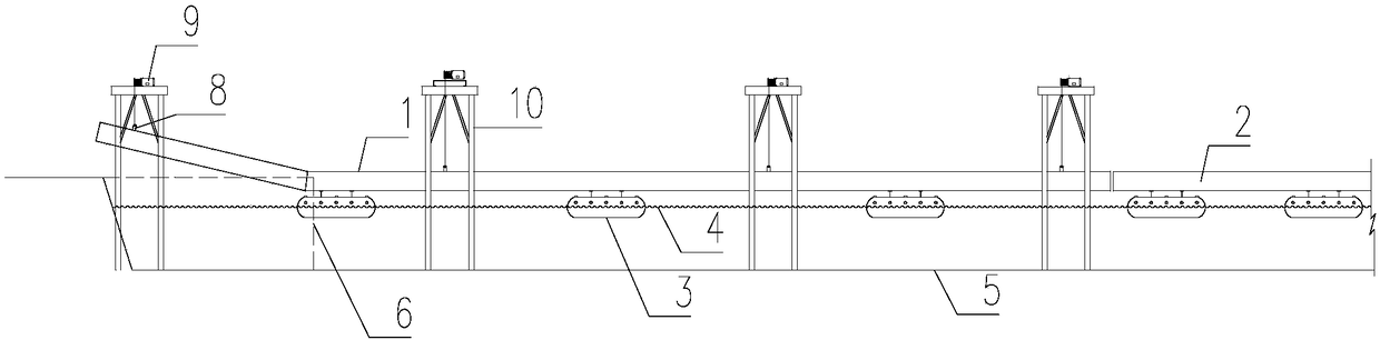
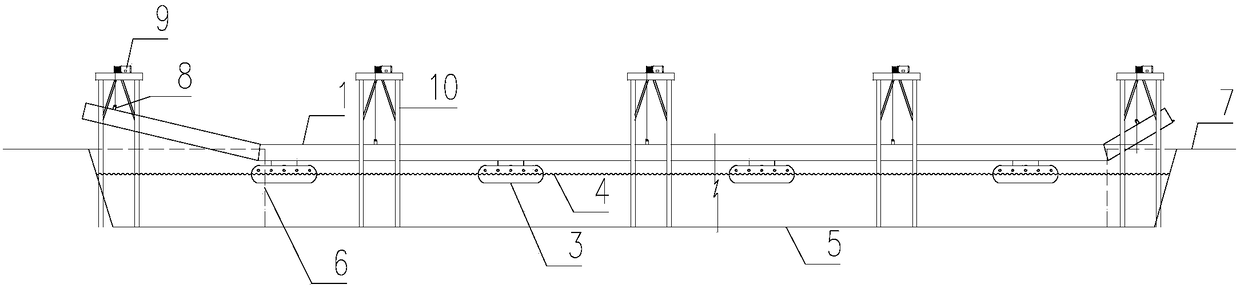
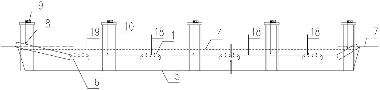
[0059] First set up an on-shore processing site near the construction of the pipeline crossing the waterway, and carry out the welding and lengthening of the standard pipe section and the transition section of the pipeline to form a steel pipe for the long unit section to be connected.

[0060] According to the length of the integral steel pipe 1, steel pipe piles 17 are applied on the waterway as anchor points for fixing the controllable buoyancy tank 3, and are used to fix the steel pipes on the water surface during water operations to prevent them from drifting with the current.

[0061] A trench for filling the steel pipes is excavated in advance on the river bed.

[0062] S...


PUM


Abstract

The invention discloses a buoyant box type water floating gantry crane pipeline sinking construction method. The method comprises steps as follows: step 1, long steel pipes are welded ashore and lifted onto a controllable buoyant box on the water surface; step 2, all small sections of steel pipes floated by the controllable buoyant box on the water surface are welded into a large section of steelpipe; step 3, a gantry crane lifts steel pipes with inclined pipe sections to be welded with the large section of steel pipe; step 4, a hydrostatic test of the steel pipes is conducted after the wholesection is mounted; step 5, the controllable buoyant box is reversely buckled on the steel pipes, and water is injected into two ends of the steel pipes to make the steel pipes to gradually sink; step 6, after the steel pipes sink, the controllable buoyant box is dismounted, the dismounted controllable buoyant box is inflated to automatically float on the water surface, and trenches are backfilled. Interface butt welding, water surface transportation, pipeline pressure test, sinking and other procedures of pipelines spanning long-distance water channels can be realized. The construction principle is simple and easy to implement, construction machinery such as a large crane is not required, the sinking positions are accurate, and the method is low in cost, safe and reliable.

Description

technical field [0001] The invention relates to a pipeline immersed pipe construction method, in particular to a floating box type water floating gantry crane pipeline immersed pipe construction method, which belongs to the field of underwater pipeline construction and is widely used in sewage plant pipelines, petroleum liquefied gas pipelines and chemical industry Cross-river installation of pipelines, etc. Background technique [0002] With the continuous development of social economy, underwater pipeline installation projects are increasing, but the current general immersed pipe construction methods, including underwater tunnel projects, generally have the following problems: [0003] (1) The overall pipeline is often used for launching, and some large-scale lifting cranes need to be arranged along the entire length of the pipeline for lifting, which is expensive and poses a great safety hazard during lifting. [0004] (2) Due to hoisting restrictions, long-distance pipe...

Claims


Application Information

Patent Timeline
Patent Type & Authority Applications(China)
IPC IPC(8): F16L1/16F16L1/24F16L1/20F16L1/26
CPCF16L1/161F16L1/20F16L1/24F16L1/26
Inventor 湛学林夏志聪陶卫军张帆
Owner CHINA FIRST METALLURGICAL GROUP
Why Eureka
Try Eureka