Device and method for measuring structural deflection

A measurement method and imaging device technology, which is applied in the field of dynamic deflection measurement, can solve the problems of high price, influence of device accuracy, and inaccurate measurement, and achieve the effect of simple structure principle, small external factors, and elimination of small inclination deformation

Pending Publication Date: 2022-02-25
CHINA-SINGAPORE INT JOINT RES INST
View PDF4 Cites 0 Cited by
  • Summary
  • Abstract
  • Description
  • Claims
  • Application Information

AI Technical Summary

Problems solved by technology

Disadvantages: The device is expensive and vulnerable to environmental conditions such as rain and fog
Disadvantages: The measurement accuracy of the detector detection circuit is subject to noise, temperature drift of the circuit and optical system. In practical applications, the measurement will be inaccurate after a large deflection of the measured object occurs
The monitoring system is greatly affected by the weather, and changes in sunlight and other light intensity will affect the accuracy of the device, and the grid-shaped shading plate cannot always be vertical during the monitoring process, and w

Method used


Image

  • Device and method for measuring structural deflection
  • Device and method for measuring structural deflection
  • Device and method for measuring structural deflection

Examples


Embodiment 1

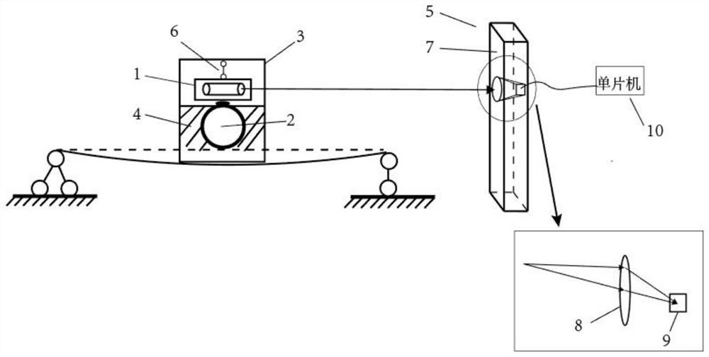
[0040] This embodiment discloses a device for measuring structural deflection, in figure 1 Among them, reference numeral 1 is a laser, 2 is a hem part, 3 is a device shell, 4 is a damping system, and 6 is a suspender. The suspender 6, the laser 1, the device shell 3 and the hem part 2 form a single pendulum system. The rod 6 and the device shell 3, the laser 1 and the suspender 6 are hinged, the laser 1 and the hem part 2 are fixed at 90 degrees, and the fixed connection is a detachable threaded connection. When the single pendulum system is stable, the laser 1 can emit horizontally collimated beam.

[0041] The hem part 2 is placed in a damping system 4, which is a high-viscosity liquid or a magnetic damper, and this high-viscosity liquid can reduce the sway of its own liquid plane when the beam deflection is measured, and can also make the The simple pendulum system that bottom part 2 constitutes stops fast. The magnetic damper is composed of a conductor and a magnetic cyl...

Embodiment 2

[0108] refer to figure 1 , the image sensor used in this specific implementation case is CCD, the sampling unit of the linear array CCD scanning device is 96, the interval of each linear array unit is 1.00mm, and the peak value of each pixel unit is 1024, the single-chip microcomputer reads through AD sampling The light value of each unit, combined with the step value of the linear CCD scanning device in the X direction, draws the image of the spot in the single-chip microcomputer, and then finds the position corresponding to the maximum brightness according to the brightness of each unit, which is the position of the spot .

Embodiment 3

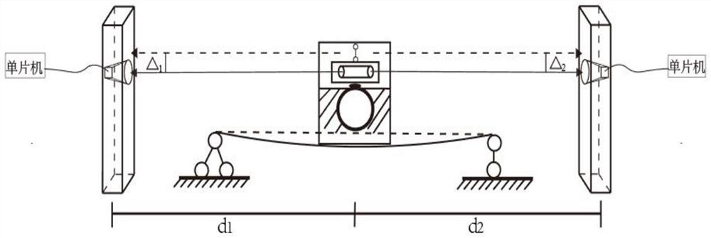
[0110] As another improved embodiment of the device of the present invention, it can be as figure 2 As shown, two lasers can be added to project the light spots on the left and right sides of the electronic scale to further reduce the influence of the inclination angle that may be caused by structural vibration, and eliminate the influence of the reciprocating vibration of the single pendulum system by averaging the moving distance of the electronic scale on both sides.

[0111]

[0112] In the formula: γ is the inclination angle of the laser, Δ 1 is the deflection measured by electronic scale 1, Δ 2 is the deflection measured by electronic scale 2, d 1 is the distance from the center of the electronic scale 1 to the center of the device, d 2 is the distance from the center of the electronic scale 2 to the center of the device.


PUM


Abstract

The invention discloses a device and a method for measuring structural deflection, the device comprises a simple pendulum system, a damping system and an electronic scale, the simple pendulum system comprises a suspender, a laser, a device shell and a lower pendulum part, the laser is installed in the device shell, and when the simple pendulum system is stable, the laser emits a horizontal collimated light beam; the lower pendulum part of the simple pendulum system is placed in the damping system and is used for eliminating vibration by increasing the damping ratio; the electronic scale comprises a leveling rod, an imaging device and a single-chip microcomputer, and the imaging device comprises a lens and an image sensor; the simple pendulum system and the electronic leveling rod are arranged in parallel, the horizontal light beam emitted by the laser device enters the lens and is projected to a photosensitive dot matrix of the image sensor after being zoomed by the lens, and the single-chip microcomputer calculates horizontal or vertical deflection according to data acquired by the image sensor; and the length of the suspender is controlled and adjusted, so that the structural damping of the device is greater than the minimum damping value required for avoiding reciprocating vibration in the free vibration reaction of the system.

Description

technical field [0001] The invention relates to the technical field of dynamic deflection measurement, in particular to a device and method for measuring structural deflection. Background technique [0002] Dynamic deflection measurement is a research hotspot in the industry and academia in recent years, but many dynamic deflection measurement methods and devices have failed to show good results in field measurements. The current bridge dynamic deflection measurement methods include CCD photoelectric method, PSD laser measurement method, seismic vibration sensor to measure dynamic deflection and other methods. (1) The CCD photoelectric method uses photoelectric image method and long-distance imaging technology, photoelectronic technology, digital image processing and related technologies, and uses the principle of photoelectric coupling to measure dynamic and static deflection. It is a long-distance non-contact measurement method. Advantages: high measurement accuracy and q...

Claims


Application Information

Patent Timeline
IPC IPC(8): G01B11/16
CPCG01B11/167
Inventor 黄仕平李开张敏
Owner CHINA-SINGAPORE INT JOINT RES INST
Why Eureka
Try Eureka