Thermal resistance test circuit and method for reverse conducting IGBT
A test circuit, reverse conduction technology, applied in the direction of single semiconductor device test, electricity measurement, electric variable measurement, etc., can solve the problem of low accuracy of thermal resistance test
- Summary
- Abstract
- Description
- Claims
- Application Information
AI Technical Summary
Problems solved by technology
Method used
Image
Examples
Embodiment Construction
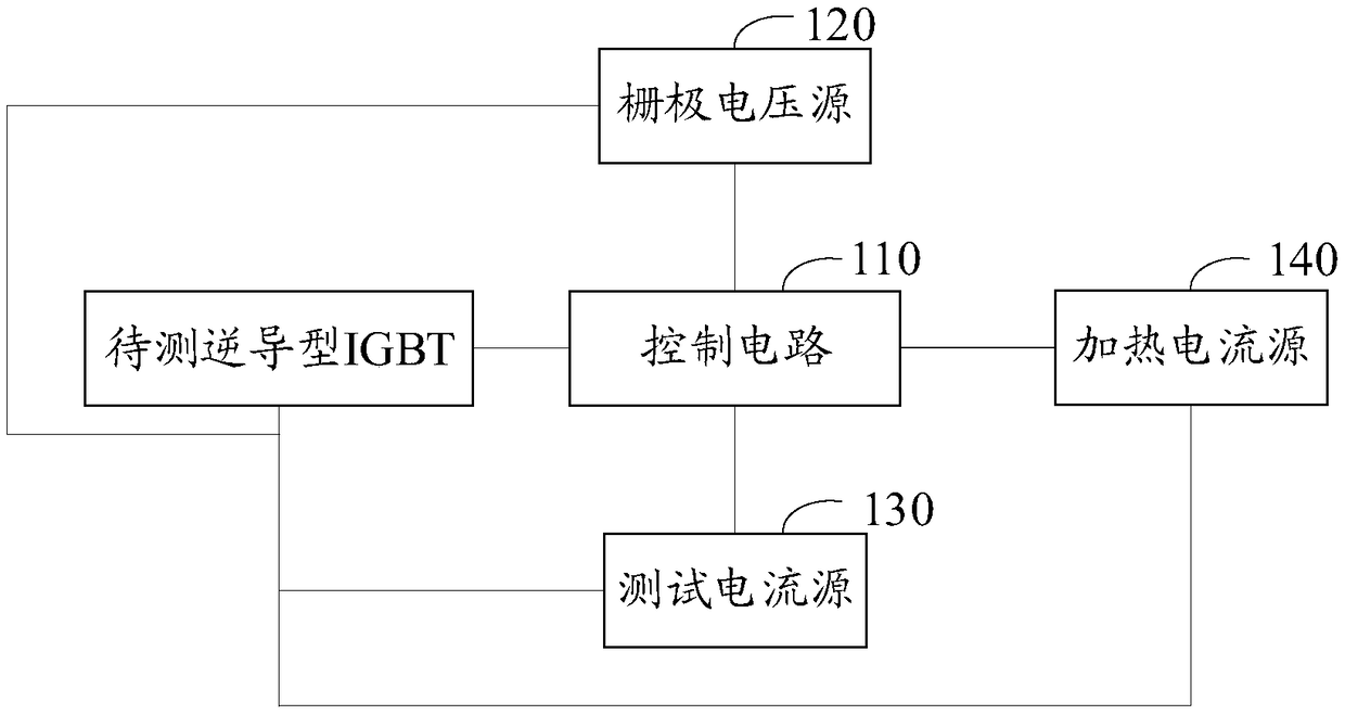
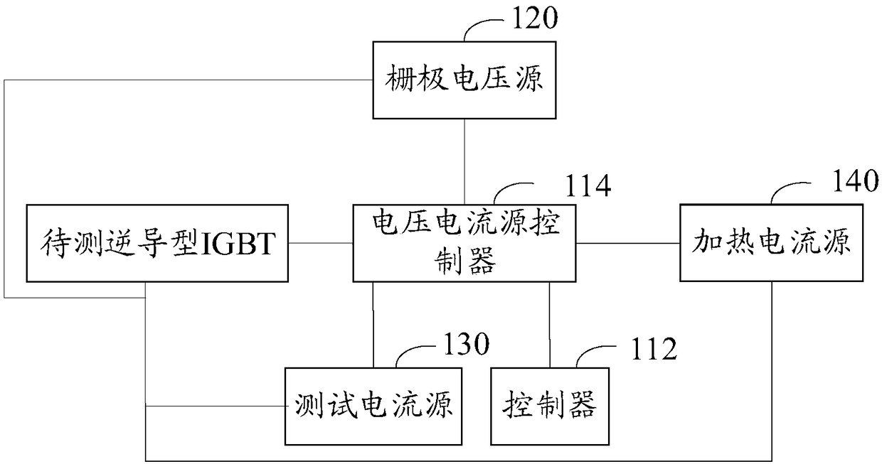
[0020] In one embodiment, such as figure 1 As shown, a thermal resistance test circuit of a reverse conduction type IGBT includes a control circuit 110, a gate voltage source 120, a test current source 130 and a heating current source 140, and the gate voltage source 120, a test current source 130 and a heating current source 140 are all connected to the control circuit 110, the gate voltage source 120, the test current source 130, the heating current source 140 and the control circuit 110 are all used to connect the reverse conduction IGBT to be tested, wherein the reverse conduction IGBT to be tested includes a gate, a collector electrode and emitter, the control circuit 110 controls the test current source 130 to output a reverse test current to the reverse conduction type IGBT to be tested, and obtains the voltage between the collector and the emitter of the reverse conduction type IGBT to be tested under the preset reverse test current condition Drop the curve that change...
PUM
 Abstract
Description
Claims
Application Information
 - R&D
- Intellectual Property
- Life Sciences
- Materials
- Tech Scout
- Unparalleled Data Quality
- Higher Quality Content
- 60% Fewer Hallucinations
Browse by: Latest US Patents, China's latest patents, Technical Efficacy Thesaurus, Application Domain, Technology Topic, Popular Technical Reports.
© 2025 PatSnap. All rights reserved.Legal|Privacy policy|Modern Slavery Act Transparency Statement|Sitemap|About US| Contact US: help@patsnap.com


