Control circuit
A technology for controlling circuits and circuits, applied in circuits, electrical components, output power conversion devices, etc., can solve problems such as overvoltage applied by gate drive circuits or MOSFETs, and achieve the effect of suppressing overcharge
- Summary
- Abstract
- Description
- Claims
- Application Information
AI Technical Summary
Problems solved by technology
Method used
Image
Examples
Embodiment approach 1
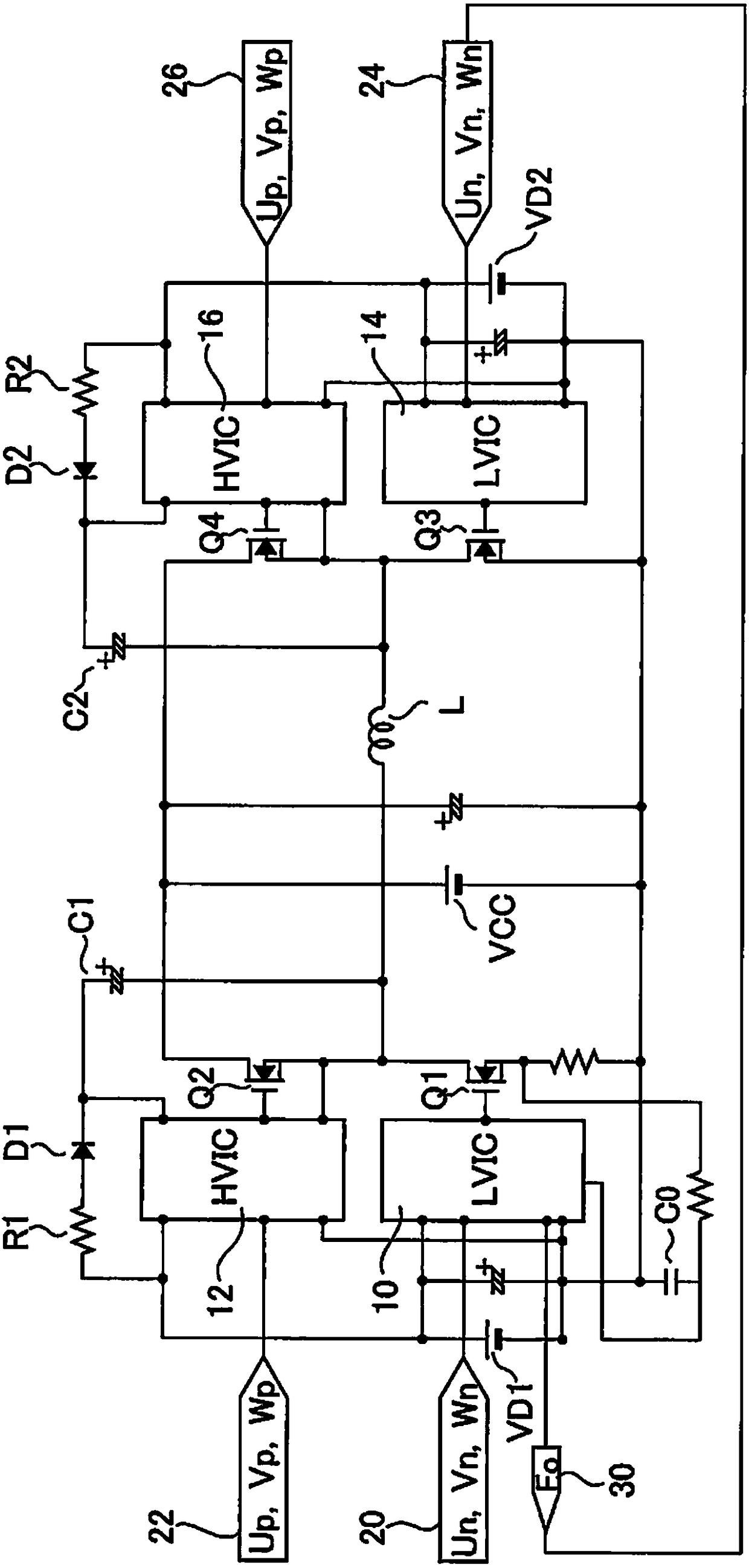
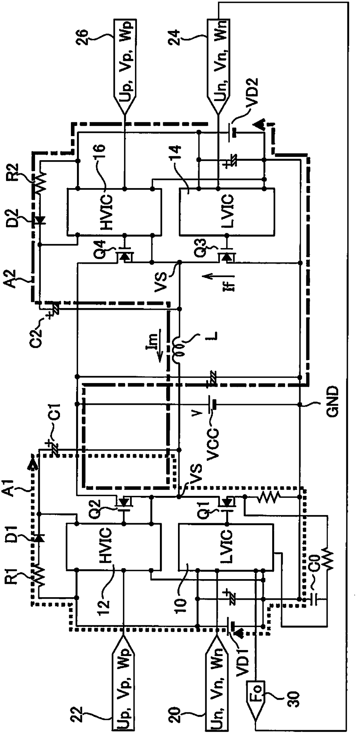
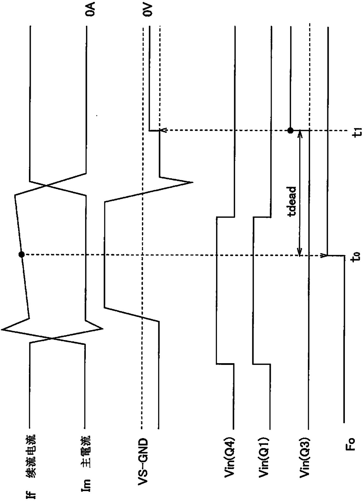
[0025] figure 1 It is a circuit diagram of the control circuit concerning Embodiment 1 of this invention. The control object of the control circuit is the inverter circuit. The inverter circuit has a totem-pole structure in which high potential side MOSFET Q2 and low potential side MOSFET Q1 are totem pole connected, and a totem pole structure in which high potential side MOSFET Q4 and low potential side MOSFET Q3 are totem pole connected. A full bridge circuit is formed by 4 MOSFETs. An AC current is supplied from the full bridge circuit to the inductance L serving as a load.
[0026] The low potential side MOSFETs Q1, Q3 are turned on and off by the first gate drive circuits 10, 14, respectively. The high potential side MOSFETs Q2 and Q4 are turned on and off by the second gate drive circuits 12 and 16, respectively. All MOSFETs are formed, for example, from silicon. The VF of the body diode when the low-potential side MOSFETs Q1 and Q3 are turned on is smaller than the...
Embodiment approach 2
[0049] The protection operation performed by the control circuit of the second embodiment is different from the protection operation of the first embodiment. In Embodiment 2, the first gate drive circuit supplies the PWM signal to the low potential side MOSFET during the protection operation.
[0050] Figure 4 It is a circuit diagram of the control circuit concerning Embodiment 2. The microcomputer 40 which generates a PWM signal is connected to the 1st gate drive circuit 10,14, and the 2nd gate drive circuit 12,16. The first gate drive circuits 10 , 14 and the second gate drive circuits 12 , 16 turn MOSFETs on and off based on PWM signals sent from the microcomputer 40 . An abnormal signal Fo is input from the first gate drive circuit 10 to the microcomputer 40 .
[0051] In the step of performing the protection operation, the PWM signal is supplied to the low potential side MOSFET Q3 by supplying the PWM signal from the microcomputer 40 to the first gate drive circuit 14...
Embodiment approach 3
[0053] The operation performed by the control circuit according to Embodiment 3 is characterized by an abnormality detection step. In Embodiment 3, the detection unit issues an abnormality signal when the temperature of the inverter circuit exceeds a preset value. When an overcurrent flows through the inverter circuit, the temperature of the inverter circuit increases, and therefore, the overcurrent is detected by detecting that the inverter circuit has become high in temperature.
[0054] Image 6 It is a configuration diagram of a control circuit according to Embodiment 3. The inverter circuit is provided with a thermometer 50 for measuring the temperature of the inverter circuit. The measurement result of this thermometer 50 is transmitted to the drive circuit 52 which drives MOSFET. The drive circuit 52 functions as a detection unit, and determines whether or not the temperature of the inverter circuit is higher than a preset value. The driving circuit 52 sends out an ...
PUM
 Abstract
Description
Claims
Application Information
 - R&D
- Intellectual Property
- Life Sciences
- Materials
- Tech Scout
- Unparalleled Data Quality
- Higher Quality Content
- 60% Fewer Hallucinations
Browse by: Latest US Patents, China's latest patents, Technical Efficacy Thesaurus, Application Domain, Technology Topic, Popular Technical Reports.
© 2025 PatSnap. All rights reserved.Legal|Privacy policy|Modern Slavery Act Transparency Statement|Sitemap|About US| Contact US: help@patsnap.com


