
Gate drive circuit of switching circuit and control circuit of switching power supply

A gate drive circuit, switching circuit technology, applied in electronic switches, high-efficiency power electronic conversion, DC circuits can reduce harmonics/ripples, etc., can solve problems such as component reliability reduction, improve noise tolerance, suppress excessive The effect of charging

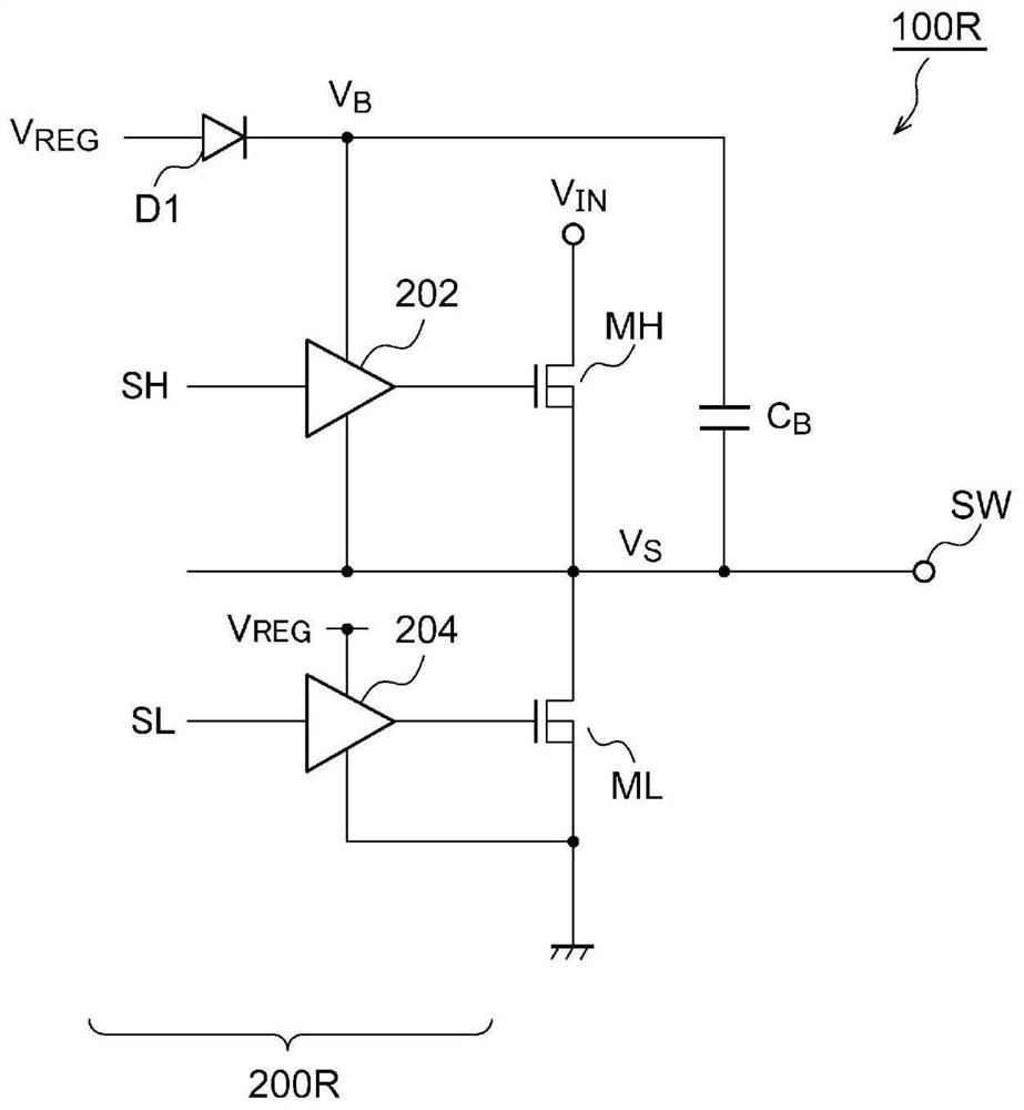
Pending Publication Date: 2022-07-08
ROHM CO LTD
View PDF1 Cites 0 Cited by
  • Summary
  • Abstract
  • Description
  • Claims
  • Application Information

AI Technical Summary

Problems solved by technology

[0010] in the bootstrap capacitor C B In the state of being overcharged, when the high-side driver 202 outputs "High", an overvoltage is applied between the gate and the source of the high-side transistor MH, and the reliability of the device will be reduced.

Method used


Image

  • Gate drive circuit of switching circuit and control circuit of switching power supply
  • Gate drive circuit of switching circuit and control circuit of switching power supply
  • Gate drive circuit of switching circuit and control circuit of switching power supply

Examples


Embodiment approach

[0042] Hereinafter, embodiments will be described with reference to the drawings. The same or equivalent components, members, and processes shown in the respective drawings are denoted by the same reference numerals, and overlapping descriptions are appropriately omitted. In addition, the embodiment does not limit the invention, but is merely an illustration, and all the features or combinations described in the embodiment are not the essential content of the invention.

[0043] In this specification, the term "the state in which the member A and the member B are connected" includes not only the case where the member A and the member B are physically directly connected, but also the fact that the member A and the member B do not substantially affect the electrical connection state of the member A and the member B. , or indirectly connected to other components that do not impair the function or effect of their combination.

[0044] Similarly, the so-called "the state in which ...


PUM


Abstract

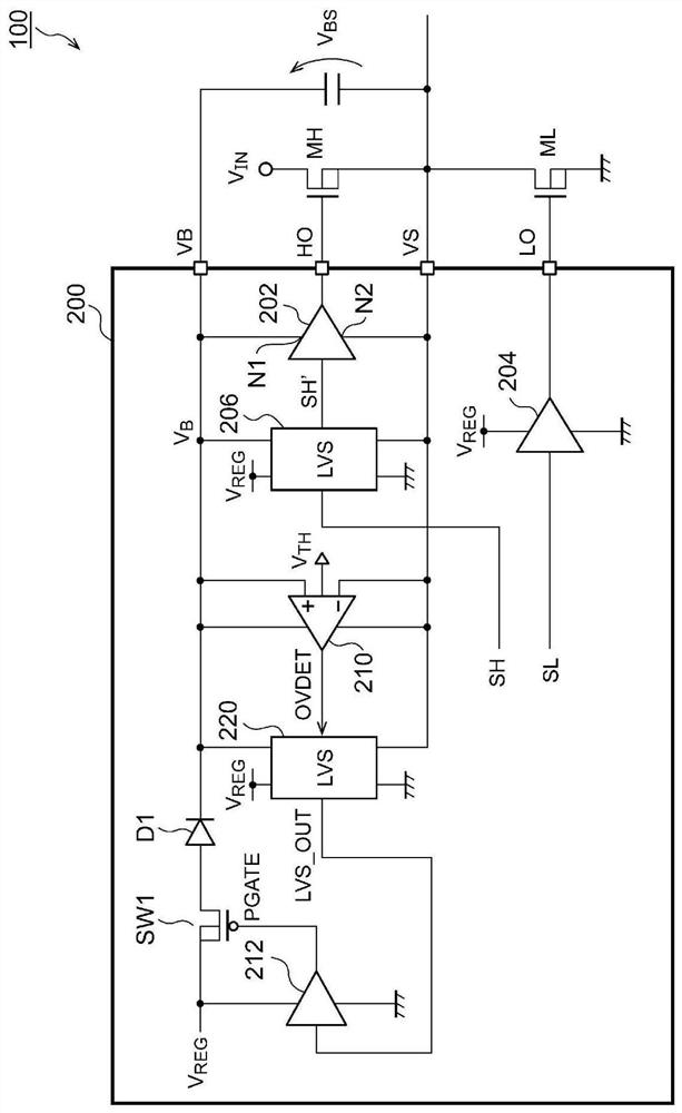
A switching circuit (100) includes an N-channel high-side transistor (MH) and a low-side transistor (ML). A switch (SW1) of a PMOS transistor and a rectifying element (D1) are connected in series between a constant voltage line for supplying a constant voltage (VREG) and a bootstrap line (VB). A comparison circuit (210) operates with a high-side power supply voltage (VBS), which is a potential difference between a bootstrap line (VB) and a switching line (VS), as a power source, and generates a detection signal (OVDET) indicating a magnitude relationship between the high-side power supply voltage (VBS) and a threshold voltage (VTH). A level shift circuit (220) lowers the level of the detection signal OVDET to a signal in which the ground voltage is "low". A PMOS driver (212) drives the switch (SW1) asynchronously with the switching of the low-side transistor (ML) on the basis of the output of the level shift circuit (220).

Description

technical field [0001] The present disclosure relates to a switching circuit. Background technique [0002] In the field of power electronics represented by DC / DC converters, AC / DC converters, and inverters, switching circuits such as half-bridge circuits and full-bridge circuits are used. [0003] figure 1 It is a circuit diagram of the switch circuit 100R. The switch circuit 100R includes a high-side transistor MH and a low-side transistor ML connected in series, and a gate drive circuit 200R that drives them. The gate drive circuit 200R controls the on / off of the high-side transistor MH and the low-side transistor ML, so that the switch terminal SW is in a high state (the input voltage V IN ) and a low state (ground voltage 0V), or between three states including a high-impedance state. [0004] The gate driving circuit 200R includes a high-side driver 202, a low-side driver 204 and a rectifying element D1. The high-side transistor MH is an N-channel transistor, and i...

Claims


Application Information

Patent Timeline
Patent Type & Authority Applications(China)
IPC IPC(8): H02M1/08
CPCH02J1/02H02M1/08H03K19/018528H03K3/356113H03K19/018521H03K2217/0081H02M1/0006H02M1/32H02M3/158H03K17/0822H03K2217/0063H03K2217/0072
Inventor 新仓浩树
Owner ROHM CO LTD
Learn More