
Redox flow battery system and method of operation of the redox flow battery

A liquid flow battery and battery unit technology, applied in fuel cells, indirect fuel cells, regenerative fuel cells, etc., can solve the problems of reduced battery efficiency and large pump loss, and achieve the effect of suppressing overcharging or overdischarging

Active Publication Date: 2018-12-18
SUMITOMO ELECTRIC IND LTD
View PDF11 Cites 0 Cited by
  • Summary
  • Abstract
  • Description
  • Claims
  • Application Information

AI Technical Summary

Problems solved by technology

[0004] In general, redox flow batteries require pumps for circulating the electrolyte in the battery cells, so pump losses occur. If the flow rate of the pump (electrolyte flow rate) is always fixed, the pump may Larger losses will lead to lower battery efficiency

Method used


Image

  • Redox flow battery system and method of operation of the redox flow battery
  • Redox flow battery system and method of operation of the redox flow battery
  • Redox flow battery system and method of operation of the redox flow battery

Examples


Embodiment approach 1

[0055]

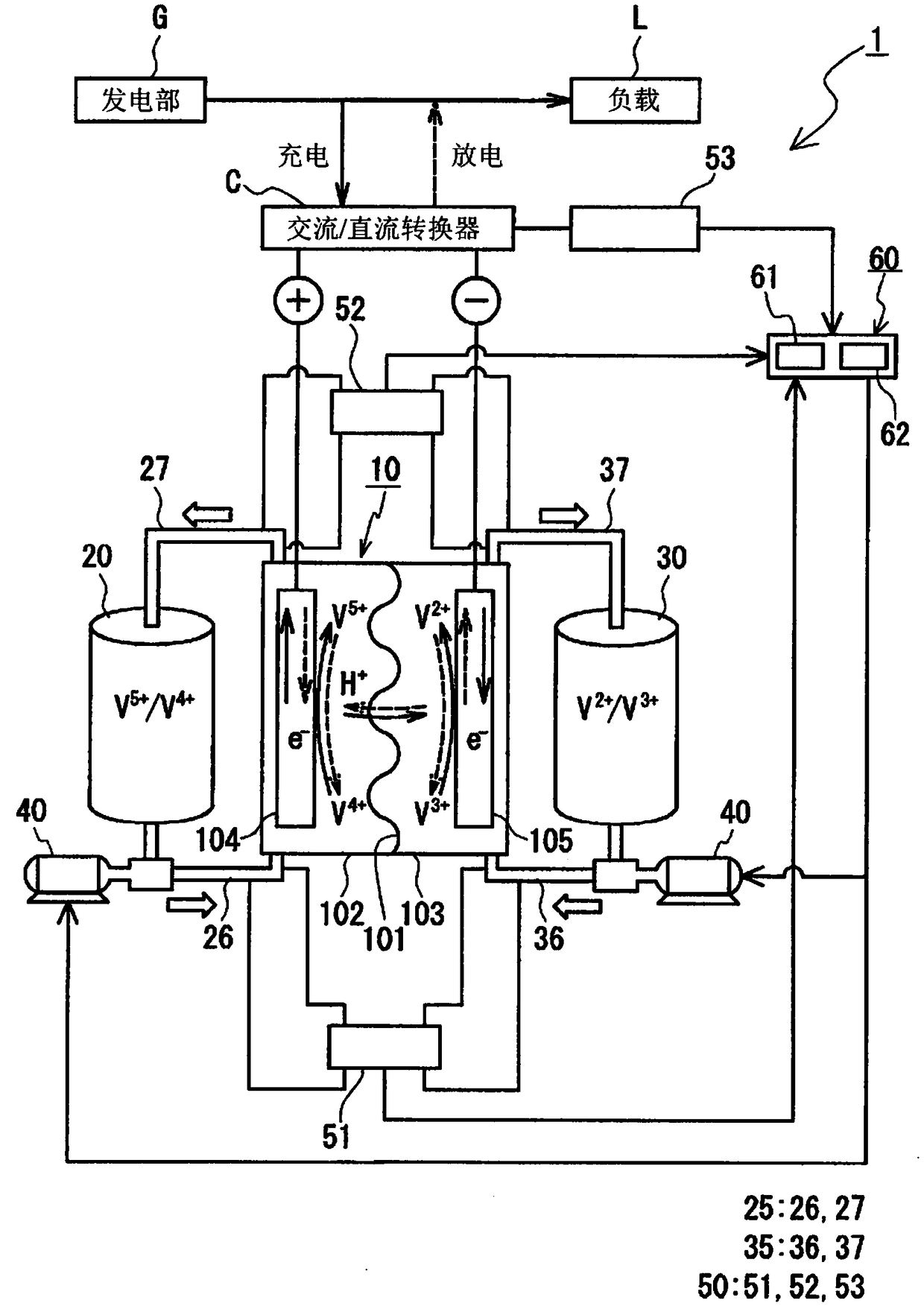
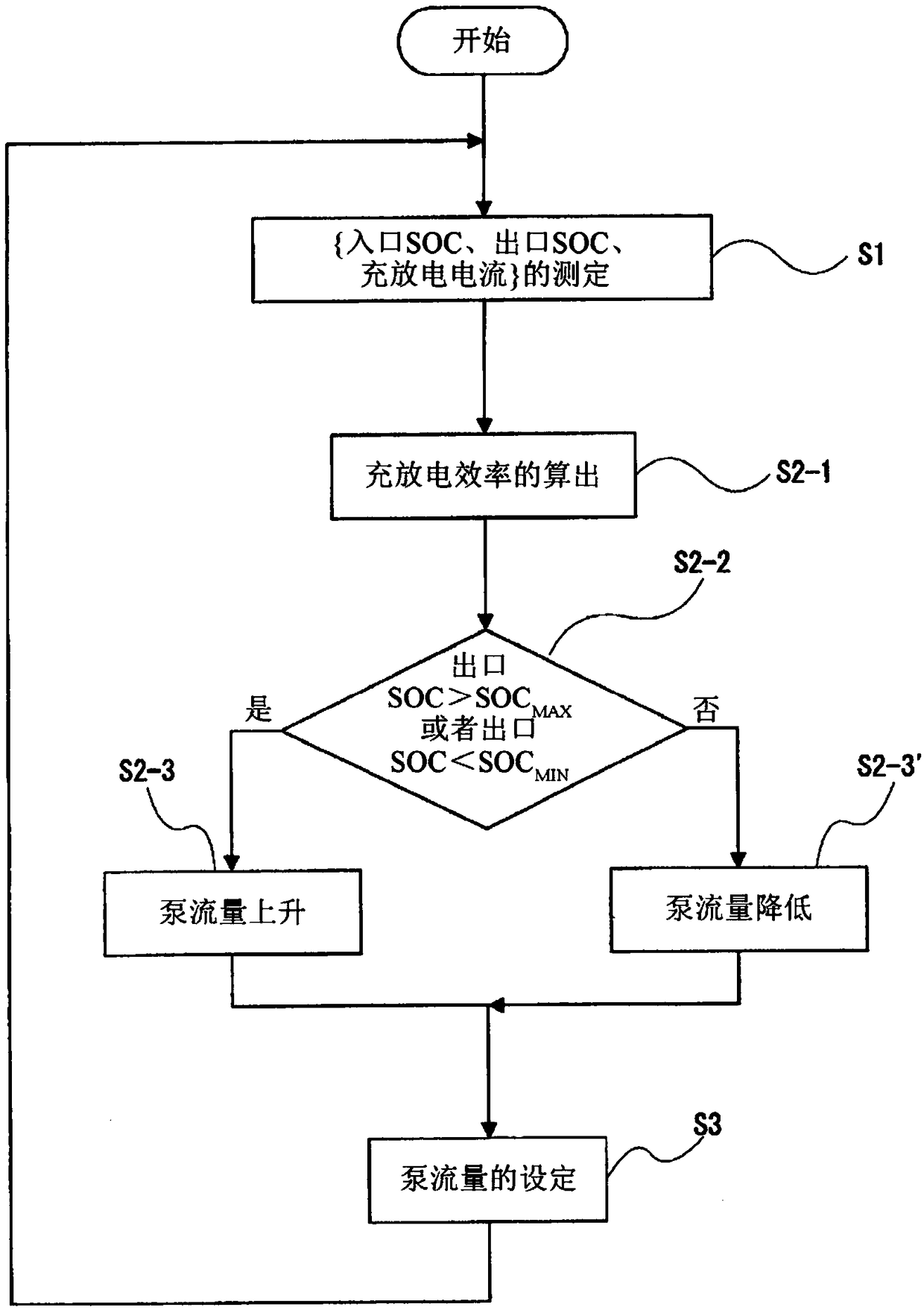
[0056] refer to Figure 1 ~ Figure 2 , the RF battery system 1 according to Embodiment 1 will be described. figure 1 The RF battery system 1 shown is connected to a power generation unit G (for example, a solar power generation device or a wind power generation device, or other general power stations) and a load L (electric power system or users) and charge the electric power supplied from the power generation unit G, or discharge the stored electric power and supply it to the load L. In addition, the RF battery system 1 includes a battery cell 10 and a circulation mechanism (reservoir, piping, pump) for supplying an electrolytic solution to the battery cell 10 .

[0057] (battery unit and circulation mechanism)

[0058] The RF battery system 1 includes a battery unit 10 . The battery cell 10 is divided into a positive electrode battery 102 and a negative electrode battery 103 by a separator 101 made of an ion permeable membrane. In addition, the RF battery syst...

Embodiment approach 2

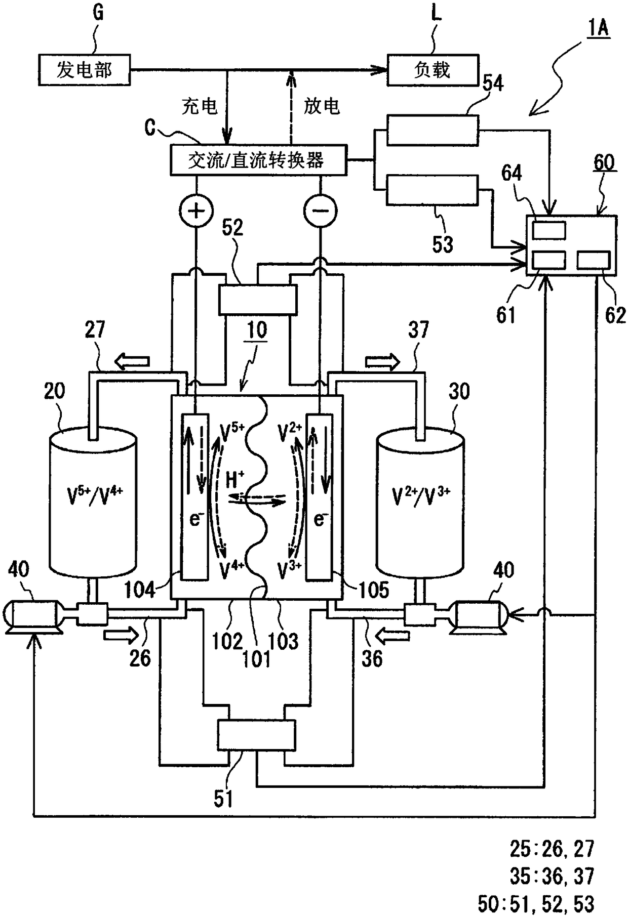
[0097] refer to Figure 3 ~ Figure 4 , the RF battery system according to Embodiment 2 will be described. image 3 The configuration of the RF battery system 1A according to Embodiment 2 shown is as follows: figure 1 The RF battery system 1 according to Embodiment 1 shown further includes a terminal voltage measurement unit 54 , and the pump control unit 60 has a terminal voltage determination unit 64 . Hereinafter, the RF battery system 1A according to Embodiment 2 will be described focusing on the points of difference from Embodiment 1 described above, and the description of the same configuration will be omitted.

[0098] (Terminal Voltage Measurement Unit)

[0099] The terminal voltage measurement unit 54 measures the terminal voltage (Vt) of the battery cell 10 . In this example, the terminal voltage measurement unit 54 uses a voltmeter and is provided in the AC / DC converter C (power converter). The measured value of the terminal voltage measured by the terminal volta...


PUM


Abstract

The invention provides a redox flow battery system and a working method of the redox flow battery for suppressing overcharging or overdischarging of an electrolyte. The redox flow battery system of the present invention includes: a pump that circulates and supplies electrolyte to the battery cells; a pump control unit that controls the flow rate of the pump; and a measurement unit that measures at least two parameters selected from the following parameters, These parameters are the inlet-side state of charge of the electrolyte supplied to the battery cell, the outlet-side state of charge of the electrolyte discharged from the battery cell, and the input to or output from the battery cell. The charge and discharge current of the pump control unit has: a pump flow calculation unit that calculates the charge and discharge efficiency of the battery unit from the parameters measured by the measurement unit, and based on the charge and discharge efficiency, from the battery unit A flow rate of the pump is determined so that the discharged electrolyte solution does not overcharge or overdischarge; and a pump flow command unit sets the flow rate determined by the pump flow calculation unit to the pump.

Description

technical field [0001] The invention relates to a redox flow battery system and a working method of the redox flow battery. In particular, it relates to a redox flow battery system that suppresses overcharge or overdischarge of an electrolyte, and an operating method of the redox flow battery. Background technique [0002] Redox flow batteries are characterized by (1) high safety, (2) long charge-discharge cycle life, (3) easy realization of large capacity, (4) continuous monitoring of state of charge (SOC: State Of Charge), etc. , can be used for a variety of purposes. Applications of redox flow batteries include, in addition to load leveling applications, applications such as instantaneous low voltage compensation and emergency power supplies, and output smoothing of natural energy such as solar power generation and wind power generation, which are being introduced on a large scale Use etc. [0003] In redox flow batteries, a positive electrode electrolyte and a negativ...

Claims


Application Information

Patent Timeline
Patent Type & Authority Patents(China)
IPC IPC(8): H01M8/18H01M8/20H01M8/04186
CPCH01M8/04186H01M8/188H01M8/20Y02E60/50H01M8/04276H01M8/04544H01M8/04604H01M8/04746
Inventor 隈元贵浩山西克也藤川一洋
Owner SUMITOMO ELECTRIC IND LTD
Learn More