
Improved double-barrel stamping mechanism for robot

A stamping mechanism and robot technology, applied in the field of robots, can solve the problems of not being able to realize multi-angle stamping, double-row stamping, affecting work efficiency, and not being able to local lighting, etc., to achieve high stamping stability, improve work efficiency, and convenient operation.

Inactive Publication Date: 2018-09-28
洪福俊
View PDF1 Cites 0 Cited by
  • Summary
  • Abstract
  • Description
  • Claims
  • Application Information

AI Technical Summary

Problems solved by technology

[0003] The application number is CN201620033490.X, a robotic multi-station automatic stamping device, although its cost is low, its production efficiency is high, and it can meet the production capacity, but it cannot realize functions such as multi-angle stamping and double-row stamping. The stamping area is small and cannot be adjusted. In the actual work process, it is not possible to perform local lighting on any angle that needs to be stamped; it cannot provide blowing and cooling functions in high temperature environments; it is not possible to place stamping plates of various sizes on the device's own Box body, when replacing the stamping plate, it is necessary to obtain the stamping plate from the box outside the device for replacement, which takes time and effort and affects work efficiency

Method used


Image

  • Improved double-barrel stamping mechanism for robot
  • Improved double-barrel stamping mechanism for robot
  • Improved double-barrel stamping mechanism for robot

Examples


Embodiment Construction

[0036] Below in conjunction with accompanying drawing, technical scheme of the present invention is described in further detail:

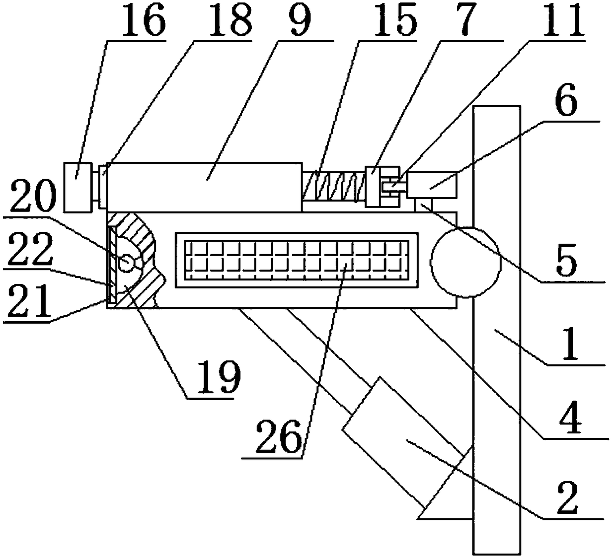
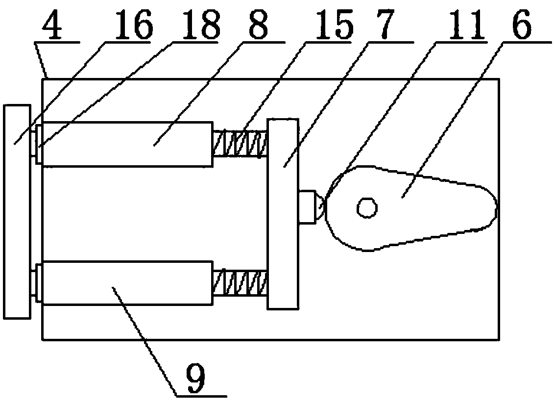
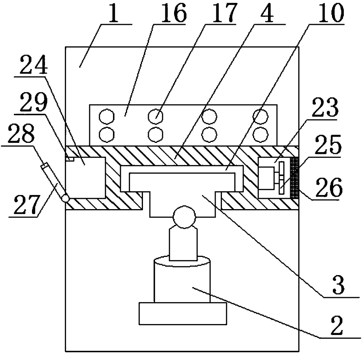
[0037] Such as Figures 1 to 4 As shown, an improved double-tube punching mechanism for a robot includes a mounting plate 1, a hydraulic cylinder 2, a slider 3, a punching platform 4, a servo motor 5, a cam 6, a double punching rod 7, a first punching cylinder 8 and a second punching cylinder. Two stamping cylinders 9; the right side wall of the mounting plate 1 is fixedly connected to the frame, the left side is fixedly connected to the fixed end of the hydraulic cylinder 2, the moving end of the hydraulic cylinder 2 is hinged to the slider 3, and the hydraulic pressure The cylinder 2 is arranged obliquely upward; the right side of the stamping platform 4 is connected to the left side of the mounting plate 1 through hinge rotation, the stamping platform 4 is arranged above the hydraulic cylinder 2, and the bottom end of the stamping platform 4 is ...


PUM


Abstract

The invention discloses an improved double-barrel stamping mechanism for a robot. The improved double-barrel stamping mechanism comprises a mounting plate, a hydraulic cylinder, a sliding block, a stamping platform, a servo motor, a cam, double stamping rods, a first stamping tube and a second stamping tube. The moving end of the hydraulic cylinder is hinged to the sliding block. The bottom end ofthe stamping platform is connected with the sliding block. The cam is connected with a shaft of the servo motor. The bottom ends of the first stamping tube and the second stamping tube are connectedwith the top end of the stamping platform. The two stamping ends of the double stamping rods are slidably connected with the inner wall of the first stamping tube and the inner wall of the second stamping tube. The right ends of the double stamping rods are connected with the cam through a rolling wheel. The two sides of the left end face of the stamping platform are provided with spherical grooves. Illuminating lamps are mounted in the two spherical grooves. The stamping platform is provided with a rectangular cavity I and a rectangular cavity II. An electric fan is connected to the inner sidewall of the rectangular cavity I. The lower edge of the rectangular cavity II is rotatably connected with a door body. The improved double-barrel stamping mechanism achieves the multi-angle stamping,double-row stamping and blowing cooling functions, is adjustable in stamping area and capable of conducting local illumination and is equipped with a stamping plate replacement cavity.

Description

technical field [0001] The invention relates to the field of robots, in particular to an improved double-tube stamping mechanism for robots. Background technique [0002] A robot is a machine device that performs work automatically. It can not only accept human command, but also run pre-programmed programs, and can also act according to the principle program formulated by artificial intelligence technology. Its task is to assist or replace human work, such as production, construction, or dangerous The concept of robots in the world has gradually converged. Generally speaking, people can accept this statement, that is, a robot is a kind of machine that realizes various functions by its own power and control ability. The United Nations Standardization Organization adopted the definition of a robot from the American Robotics Association: "A programmable and multifunctional manipulator; or a specialized system that can be changed by a computer and programmed to perform differen...

Claims


Application Information

Patent Timeline
Patent Type & Authority Applications(China)
IPC IPC(8): B21D22/02B21D37/16B21D37/04B30B15/00
CPCB21D22/02B21D37/04B21D37/16B30B15/00
Inventor 洪福俊
Owner 洪福俊
Learn More