Projection welding nut leakage resistance and positioning welding mechanism

A technology of positioning welding and projection welding nuts, which is applied in welding equipment, resistance welding equipment, metal processing equipment, etc., can solve the problems of production line interruption, downgrade processing, and vehicle scrapping, etc., and achieves low cost investment, stable structure, and reliable positioning. Effect

Active Publication Date: 2018-09-28
CHERY AUTOMOBILE CO LTD
View PDF9 Cites 0 Cited by
  • Summary
  • Abstract
  • Description
  • Claims
  • Application Information

AI Technical Summary

Problems solved by technology

The assembly sequence is the fixed assembly on the front seat belt slide → the body of the B-pillar inner panel → the front retractor installation plate. The current production mode of the assembly mainly has the following problems: the fixed assembly on the front seat belt slide is replaced by the B-pillar The inner plate is covered by the main body. When the seat belt slide plate is missing welded nuts, it cannot be visually inspected normally and flows into the subsequent process. Only when the retractor high-profile device is assembled in the final assembly and it is found that it cannot be tightened can the nuts be leaked welded. At this time, the production line is blocked. Sudden interruption, the whole vehicle is scrapped or downgraded, resulting in relatively large economic losses

Method used


Image

  • Projection welding nut leakage resistance and positioning welding mechanism
  • Projection welding nut leakage resistance and positioning welding mechanism

Examples


Embodiment Construction

[0019] Below with reference to the accompanying drawings, through the description of the implementation examples, the specific embodiments of the present invention, such as the shape, structure, mutual position and connection relationship between each part, the role and working principle of each part, etc., will be further described. detailed description of the .

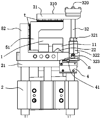
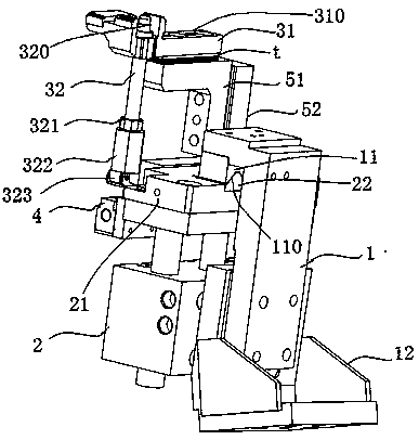
[0020] Such as figure 1 , 2 The projection welding nut leak-proof and positioning welding mechanism of the present invention includes a base 1, a guide rod mechanism 2 is provided on the side of the base 1, and a positioning guide mechanism is arranged above the guide rod mechanism 2, and the positioning guide mechanism includes a positioning guide block 31, Positioning guide pin 32, the upper surface of positioning guide block 31 is the conforming surface 310 of the assembly part used to fit the mounting nut, the upper end of positioning guiding pin 32 is connected with positioning guide block 31 and passes throug...


PUM


Abstract

The invention provides a projection welding nut leakage resistance and positioning welding mechanism. With the projection welding nut leakage resistance and positioning welding mechanism, the problemsabout positioning and leakage resistance of projection welding nuts can be solved at the same time. The projection welding nut leakage resistance and positioning welding mechanism comprises a base. Aguide rod mechanism is arranged beside the base. A positioning guide mechanism is arranged above the guide rod mechanism. The positioning guide mechanism comprises a positioning guide block and a positioning pilot pin. The upper surface of the positioning guide block is a profile conforming face of an assembly part used for being attached to an installation nut. The upper end of the positioning pilot pin is connected with the positioning guide block and penetrates through the profile conforming face. The part, penetrating out of the profile conforming face, of the positioning pilot pin is provided with a circular-truncated-cone-shaped positioning portion with the reducing diameter. An inclined face with an adjustable inclination angle is arranged at the bottom of the lower end of the positioning pilot pin. A guide rod on the upper part of the guide rod mechanism is provided with a connecting plate. A mechanical valve is arranged beside the connecting plate. The mechanical valve is arranged below the inclined face. A positioning stop dog is arranged beside the connecting plate. A shape conforming positioning stop dog used in cooperation with the positioning stop dog in the travel of the guide rod mechanism is arranged on the base.

Description

technical field [0001] The invention relates to the technical field of auxiliary equipment for automobile production, in particular to a projection welding nut leakage prevention and positioning welding mechanism. Background technique [0002] In the general car body welding process, the B-pillar inner panel body assembly, the front safety belt slide plate fixing assembly, and the front retractor mounting plate are welded together to form the B-pillar inner panel assembly. The assembly sequence is the fixed assembly on the front seat belt slide → the body of the B-pillar inner panel → the front retractor installation plate. The current production mode of the assembly mainly has the following problems: the fixed assembly on the front seat belt slide is replaced by the B-pillar The inner plate is covered by the main body. When the seat belt slide plate is missing welded nuts, it cannot be visually inspected normally and flows into the subsequent process. Only when the retracto...

Claims


Application Information

Patent Timeline
Patent Type & Authority Applications(China)
IPC IPC(8): B23K11/36B23K11/14
CPCB23K11/14B23K11/36
Inventor 方银胜孟祥新王树辉张健芮世力李新国王中伟
Owner CHERY AUTOMOBILE CO LTD
Why Eureka
Try Eureka