Water guide laser processing method and system

A laser processing method and laser processing technology, which are applied in laser welding equipment, metal processing equipment, manufacturing tools, etc., can solve problems such as ablation nozzles, water beam deflection, and easy damage, so as to reduce equipment costs and maintenance costs, Reducing the requirements for laser focus accuracy and stabilizing processing quality

Pending Publication Date: 2018-09-28
GUILIN UNIV OF ELECTRONIC TECH
View PDF8 Cites 7 Cited by
  • Summary
  • Abstract
  • Description
  • Claims
  • Application Information

AI Technical Summary

Problems solved by technology

[0003] Obviously, many excellent characteristics of water-guided laser processing in the field of precision processing make it have great application prospects, but the existing water-guided laser processing device has an obvious defect: the coupling of laser and water beam is difficult
In addition, during the processing process, if the water beam generated by the nozzle is affected by the external environment, it may be pulled away, which will also cause an accident of laser ablation nozzle
[0006] To complete the laser processing cut below 28μm, the diameter of the micro-water beam should not exceed 22μm, then the diameter of the nozzle microhole should not exceed 26μm, and the thickness of the nozzle is generally 1-2mm, which requires high-hardness materials such as diamonds and diamonds. In general, the processing of through holes with a length of more than 1 mm and a diameter of 26 μm or less requires a very high degree of smoothness on the processed surface, which puts extremely strict requirements on the processing of the nozzle, resulting in a higher cost of the nozzle
[0007] The cost of the nozzle is high and it is easy to be damaged, which makes the existing water-guided laser equipment have high investment and maintenance costs, which hinders the promotion and use of the water-guided laser process

Method used


Image

  • Water guide laser processing method and system
  • Water guide laser processing method and system
  • Water guide laser processing method and system

Examples


Embodiment 2

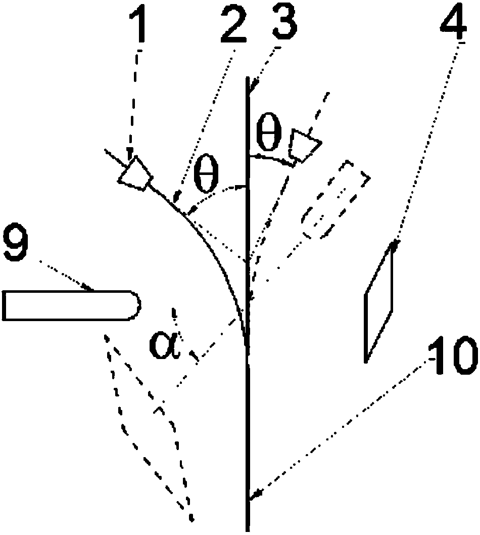
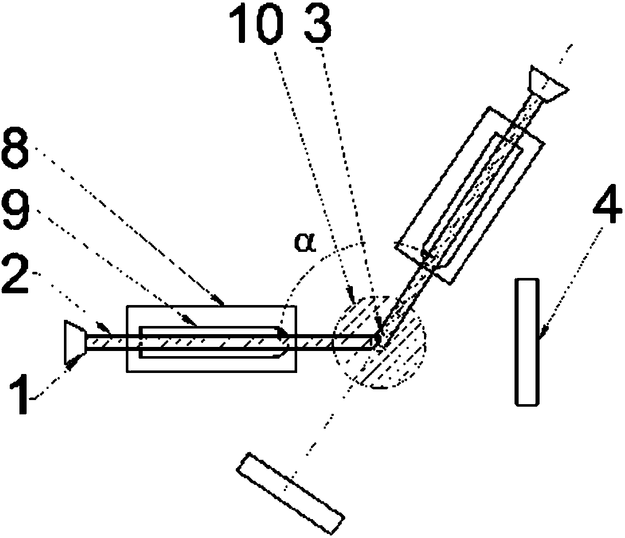
[0035] Embodiment 2 of this water guide laser processing system is as figure 2 and 3 As shown, this example is equipped with 2 sets of water beam deflecting devices, and the water beams deflected by the 2 sets of water beam deflecting devices are combined into a total water beam 10 flowing vertically downward, and the laser beam 3 is focused in the total water beam 10 . The laser beam 3 coincides with the centerline of the total water beam 10 . The angle α between the centerlines of the electrode rods of the two sets of deflecting water beam devices and the vertical plane formed by the centerlines of the laser beams 3 is 120°.

[0036] One of the 2 sets of deflecting water beam devices in this example is the same as the deflecting water beam device described in Embodiment 1 above.

[0037] The distance between the outlet of nozzle 1 and the center line of laser beam 3 of another set of deflecting water beam device is 25 mm, and the distance between the outlet of nozzle 1 and ...

Embodiment 3

[0039] Embodiment 3 of the water-conducting laser processing system is as follows: Figure 4 As shown, this example is equipped with 3 sets of deflecting water beam devices as described in Embodiment 1 above, and the water beams deflected by each set of deflecting water beam devices are combined into a total water beam 10 flowing vertically downward, and the laser beam 3 is focused on the total water beam 10. Inside the water beam 10. The included angle between the centerlines of the electrode rods of the three sets of deflecting water beam devices and the vertical plane formed by the three centerlines of the laser beams is 120°.


PUM


Abstract

The invention discloses a water guide laser processing method and system. A non-uniform strong electric field generated by an electrode acts on a water beam; the deflected water beam falls verticallydownward; the laser focuses into the vertically downward water beam; and the water beam guides the laser to act on a workpiece. The workpiece is fixed to the bottom face of a water groove in a workingtable; a set of deflected water beam device is arranged; the water beam produced by a nozzle is on the same plane with the central line of the laser beam; the electrode is arranged under the water beam; the water beam is deflected vertically downward in the non-uniform strong electric field of the electrode; the laser focuses into the vertically downward water beam; and the water beam guides thelaser beam to act on the workpiece on the working table. Two to five sets of deflected water beam devices can be arranged, and all the water beams converge into a vertically downward total water beamto guide the laser beam. When the laser softens the surface material of the workpiece in a high temperature, the water beam cools the machined area at the same time, and therefore the thermal damage is reduced; the nozzle aligned with the center line of the laser beam is not needed and the nozzle is not ablated; the significantly reduced cost of the device facilitates the water guide laser being popularized and applied.

Description

technical field [0001] The invention relates to water-guiding laser processing technology, in particular to a water-guiding laser processing method and system, which uses a non-uniform electric field to deflect the flow direction of water beams to avoid laser ablation to generate water flow nozzles. Background technique [0002] The water-guided laser processing method focuses the laser on the inside of the thin water beam, and the laser is totally reflected inside the water beam and propagates along the water beam. While the laser ablates the surface of the workpiece, the fine water beam impacts the workpiece to remove material to complete the cutting process. Due to the extremely small diameter of the water beam, the water-guided laser processing realizes micro-damage cutting, and because the water beam scours the molten material and chips generated by the laser, the processed section is smooth without obvious recasting layer, which significantly improves the processing qua...

Claims


Application Information

Patent Timeline
Patent Type & Authority Applications(China)
IPC IPC(8): B23K26/38B23K26/146B23K26/70
CPCB23K26/146B23K26/38B23K26/70B23K26/702
Inventor 龙芋宏黄宇星刘清原周嘉李海建赵要武杨林帆焦辉
Owner GUILIN UNIV OF ELECTRONIC TECH
Why Eureka
Try Eureka