Hydraulic mechanical positioning and installing device flexible to operate

A hydraulic machinery, positioning and installation technology, applied in the direction of metal processing, metal processing equipment, manufacturing tools, etc., can solve the problems of not being able to move up and down, time-consuming and laborious, and only rotating, so as to protect the staff, expand the scope of use, and reduce the burden. Effect

Pending Publication Date: 2018-09-28
GAOYOU INST CO LTD DALIAN UNIV OF TECH
View PDF0 Cites 4 Cited by
  • Summary
  • Abstract
  • Description
  • Claims
  • Application Information

AI Technical Summary

Problems solved by technology

When installing the existing silicon carbide rod high-temperature components, it needs to be plugged upward from the inner wall of the furnace or plugged into the rod hole from left to right. Due to the large depth inside the furnace body of the equipment, the artificial arm cannot reach it, and it is not possible to use other fixtures. It is easy to locate, time-consuming and labor-intensive, and it is easy to break the silicon carbide rod, resulting in waste and waste. With the application of hydraulic manipulators more and more widely, there have been problems with the single structure of hydraulic manipulators, such as only rotating but not moving up and down, or only up and down The problem that the movement cannot be rotated, and the existing manipulator is inconvenient to use, occupies a large area, and is heavy; therefore, it is necessary to design a hydraulic mechanical positioning installation device with flexible operation

Method used


Image

  • Hydraulic mechanical positioning and installing device flexible to operate
  • Hydraulic mechanical positioning and installing device flexible to operate
  • Hydraulic mechanical positioning and installing device flexible to operate

Examples


Embodiment Construction

[0022] The following will clearly and completely describe the technical solutions in the embodiments of the present invention with reference to the accompanying drawings in the embodiments of the present invention. Obviously, the described embodiments are only some, not all, embodiments of the present invention. Based on the embodiments of the present invention, all other embodiments obtained by persons of ordinary skill in the art without making creative efforts belong to the protection scope of the present invention.

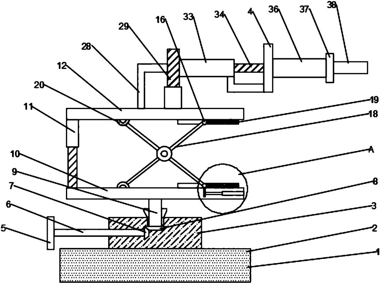
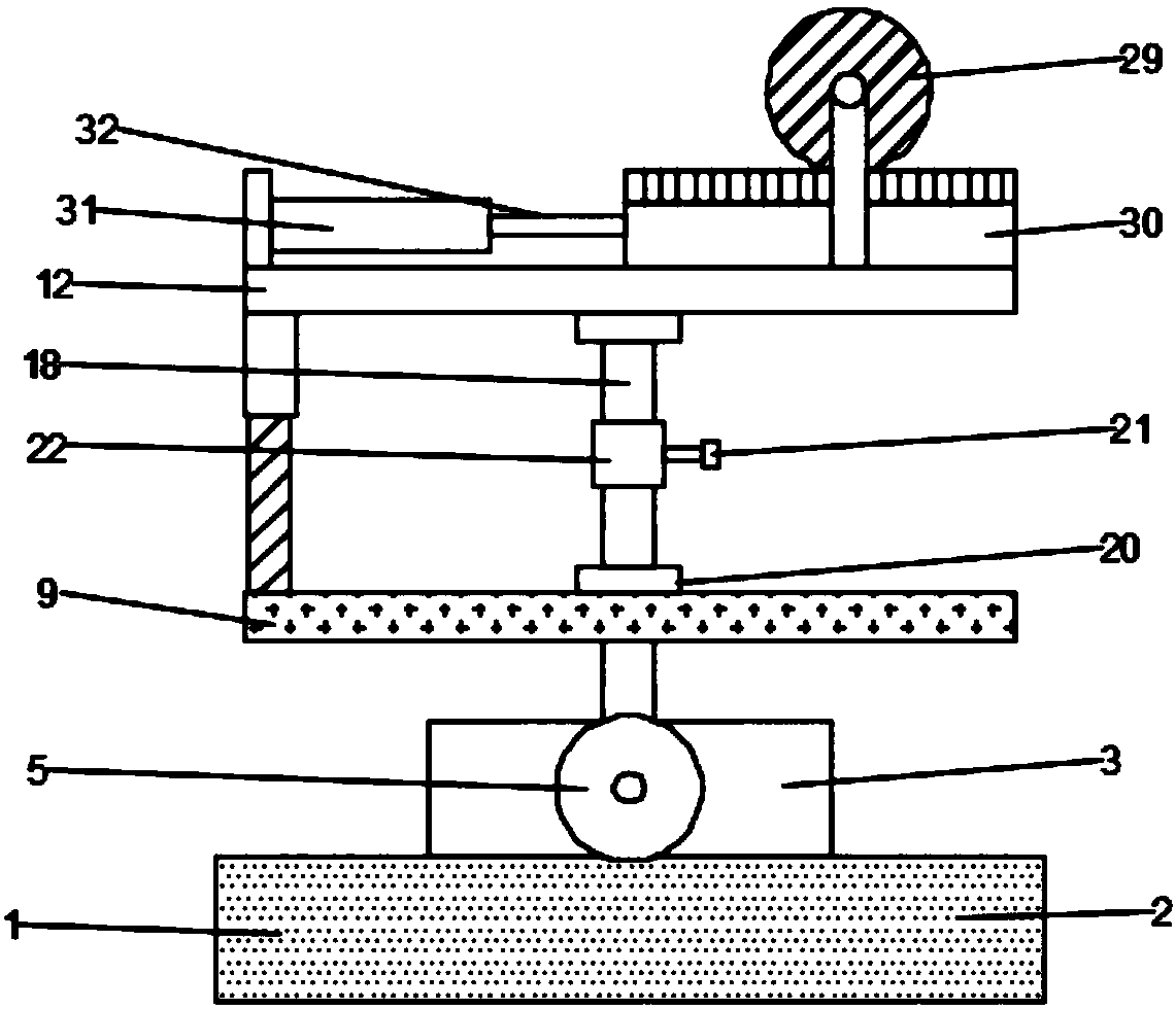
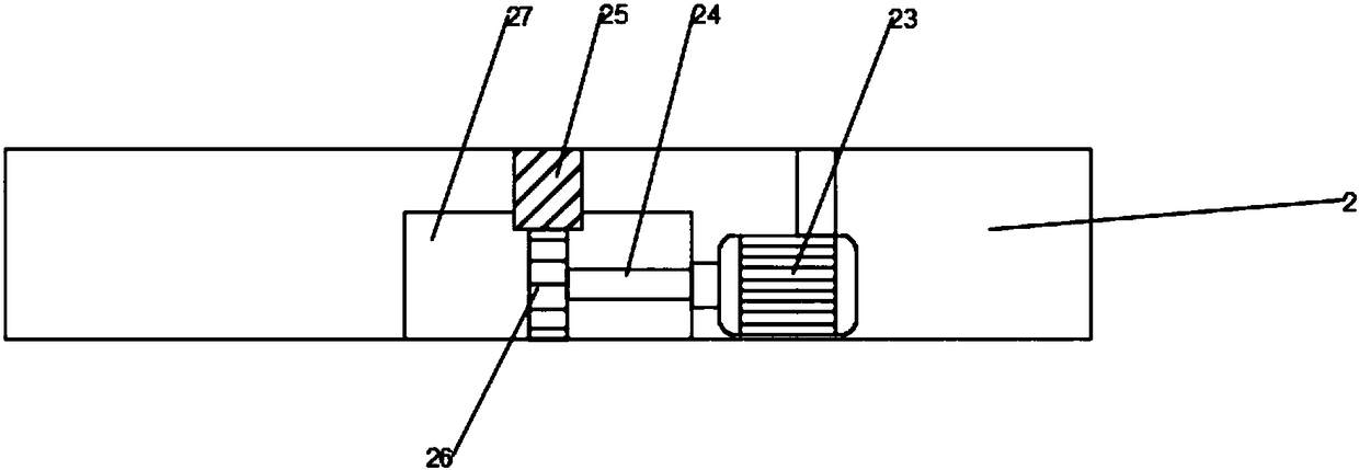
[0023] see Figure 1~6, in an embodiment of the present invention, a flexible hydraulic mechanical positioning and installation device includes a body 1, a driving box 2, a support base 3 and a grabbing device 4, the bottom of the body 1 is equipped with a driving box 2, and the driving box 2 An inner cavity is provided inside, and a support base 3 is slidably installed in the middle position of the upper surface of the drive box 2, and the bottom of the suppo...


PUM


Abstract

The invention discloses a hydraulic mechanical positioning and installing device flexible to operate. The hydraulic mechanical positioning and installing device comprises a machine body, a driving boxand a supporting base, and is characterized in that the driving box is arranged at the bottom of the machine body, an inner cavity is formed in the driving box, the supporting base is arranged in themiddle of the upper surface of the driving box in a sliding mode, a manual rotating disc is arranged on the left side of the supporting base, a first rotary shaft is welded to the middle of the rightside of the manual rotating disc, a first bevel gear is welded to the right end of the first rotary shaft, a second bevel gear is arranged on the right upper portion of the first bevel gear, a secondrotary shaft is fixedly welded above the second bevel gear, and the upper end of the second rotating shaft is connected with a lower positioning plate. The device is convenient to operate, and the height and the horizontal position of the grabbing device can be flexibly adjusted; the grabbing angle can be adjusted according to the actual situation, the application range is expanded, and the burden of workers is relieved; and meanwhile, people can be prevented from directly contacting a silicon carbon rod, so that the effect of protecting workers is achieved.

Description

technical field [0001] The invention relates to the technical field of hydraulic mechanical equipment, in particular to a hydraulic mechanical positioning and installation device with flexible operation. Background technique [0002] Silicon carbide rods are rod-shaped and tubular non-metallic high-temperature electric heating elements made of high-purity green hexagonal silicon carbide as the main raw material, processed into blanks according to a certain material ratio, and sintered at 2200°C for high-temperature siliconization, recrystallization and sintering. The normal operating temperature in an oxidizing atmosphere can reach 1450 ° C, and the continuous use can reach 2000 hours. It is convenient, safe and reliable to use silicon carbide rods for heating. It has been widely used in high-temperature fields such as electronics, magnetic materials, powder metallurgy, ceramics, glass, semiconductors, analysis and testing, and scientific research. Electric heating elements...

Claims


Application Information

Patent Timeline
Patent Type & Authority Applications(China)
IPC IPC(8): B23P19/00
CPCB23P19/001
Inventor 李强
Owner GAOYOU INST CO LTD DALIAN UNIV OF TECH
Why Eureka
Try Eureka