Automatic clamping device of lathe

A clamping device and automatic technology, applied in the direction of positioning device, clamping, support, etc., to achieve the effect of avoiding workpiece falling off, ensuring processing safety, and avoiding safety accidents

Pending Publication Date: 2018-09-28
胡文正
View PDF21 Cites 1 Cited by
  • Summary
  • Abstract
  • Description
  • Claims
  • Application Information

AI Technical Summary

Problems solved by technology

[0003] The present invention mainly solves the technical problems existing in the prior art, thereby providing a simple structure, easy to use, convenient for the user to clamp and fasten the workpiece, effectively avoiding the safety problem that the workpiece is not firmly clamped, and ensuring the safety of the user. Lathe automatic clamping device for processing convenience and processing safety

Method used


Image

  • Automatic clamping device of lathe
  • Automatic clamping device of lathe
  • Automatic clamping device of lathe

Examples


Embodiment Construction

[0026] The preferred embodiments of the present invention will be described in detail below in conjunction with the accompanying drawings, so that the advantages and features of the present invention can be more easily understood by those skilled in the art, so as to define the protection scope of the present invention more clearly.

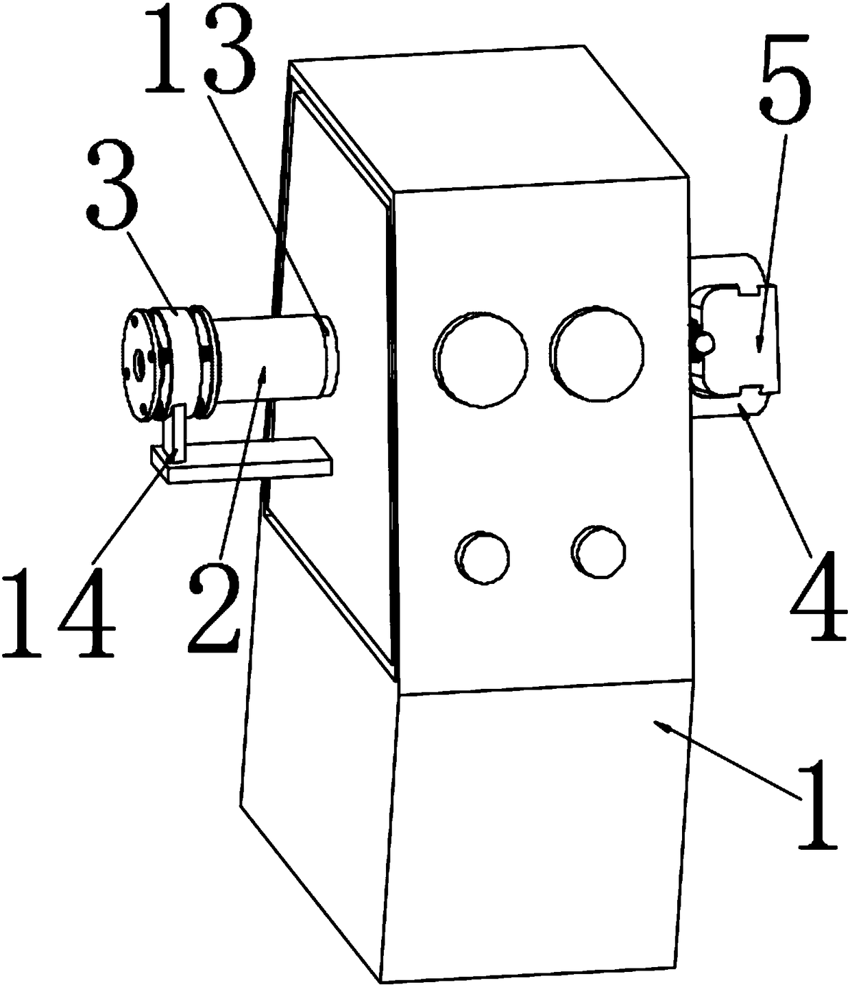
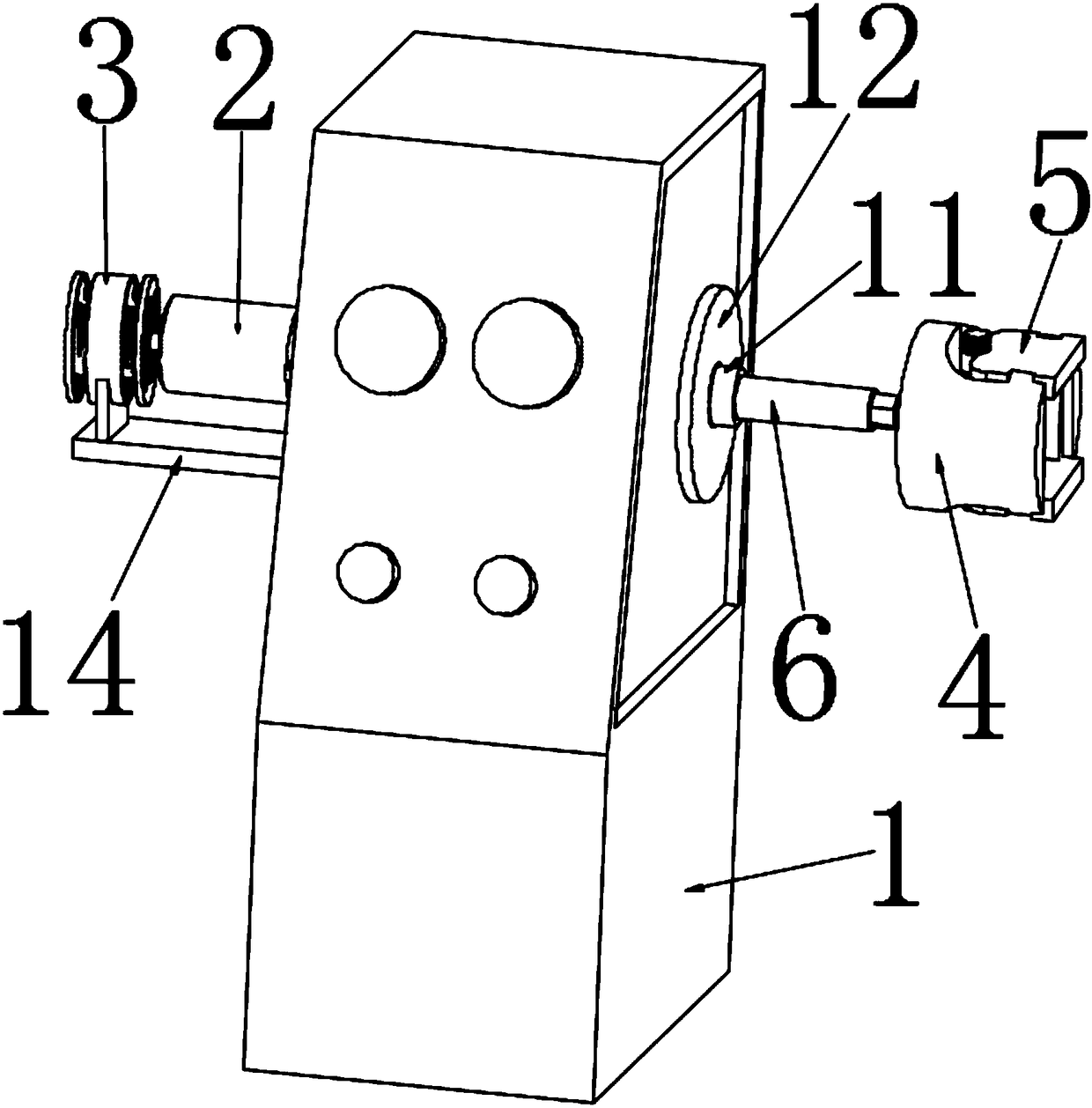
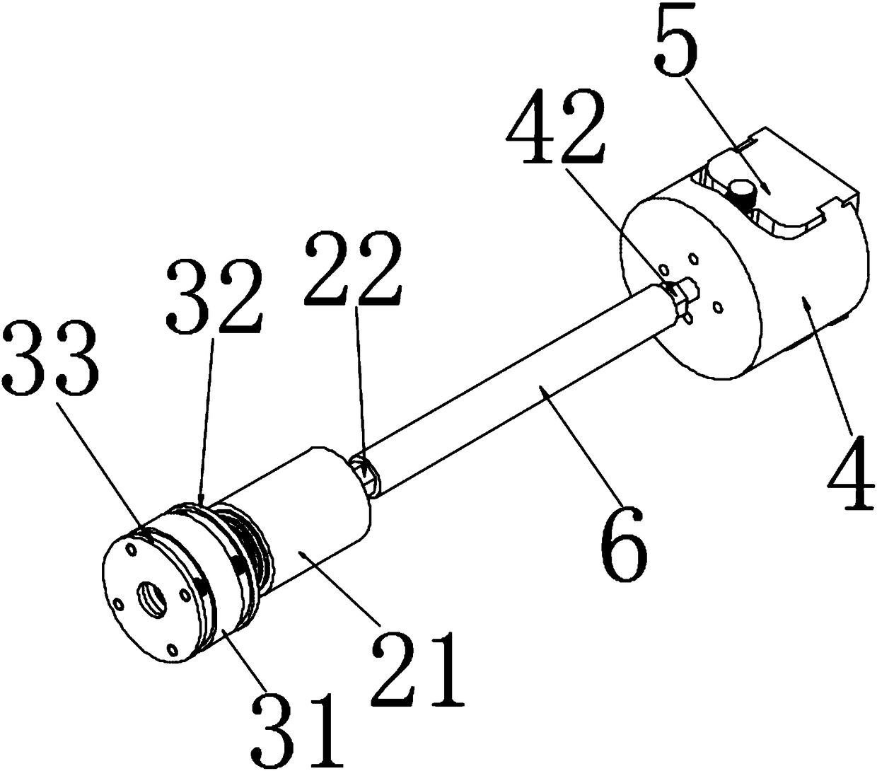
[0027] Such as Figure 1 to Figure 9 A lathe automatic clamping device shown includes a core tube 6 arranged inside the lathe main shaft 11, a turntable mechanism 4 connected to the front of the lathe main shaft 11, a power mechanism 2 connected to the rear of the lathe main shaft 11, and a turntable The clamping mechanism 5 that the mechanism 4 is connected with each other, and the control mechanism 3 that is connected with the lathe 1 and cooperates with the power mechanism 2, the power mechanism 2 includes a motor 21, and an adapter ring 24 connected to the motor 21 rear, the motor 21 The front end of the crankshaft is connected with the front...


PUM


Abstract

The invention provides an automatic clamping device of a lathe. The automatic clamping device comprises a control mechanism, a power mechanism, a rotating disc mechanism and a clamping mechanism. A core pipe is connected between the power mechanism and the rotating disc mechanism, the power mechanism comprises a motor and a connection ring connected to the rear of the motor, the front end of a motor shaft of the motor is connected with a front chuck, the rear end of the motor shaft of the motor is connected with a connection rod, the control mechanism comprises an electromagnetic disc, a suction disc and a guide disc, the electromagnetic disc is located between the suction disc and the guide disc, an elastic part is arranged between the electromagnetic disc and the suction disc, an elasticpart is arranged between the electromagnetic disc and the guide disc, the outer surface of the guide disc is provided with an annular groove, the annular groove and the connection ring are mutually matched, and the electromagnetic disc, the suction disc and the guide disc are all arranged in the center of the connection rod. According to the automatic clamping device of the lathe, whether the motor is powered on or off can be controlled through the electromagnetic disc, a user can control work of the clamping mechanism through the motor, and the user can clamp workpieces conveniently.

Description

technical field [0001] The invention relates to a clamping device, in particular to an automatic clamping device for a lathe. Background technique [0002] At present, the process of machining workpieces on lathes is generally clamped and fastened by a three-jaw chuck, but this conventional clamping jaw can not only process workpieces with regular shapes, but also requires users to manually clamp and fasten the workpieces. It greatly affects the convenience of the user's operation, and it is also very easy for the workpiece to break away from the gripper due to the user's carelessness or insufficient fastening force, which affects the user's operation safety in the process of processing, and some conventional automatic The grippers are difficult to install on a lathe, which affects the user's convenience of operation, and the power mechanism and clamping mechanism of this type of automatic gripper are prone to damage, which is not conducive to the user's debugging and replac...

Claims


Application Information

Patent Timeline
Patent Type & Authority Applications(China)
IPC IPC(8): B23Q3/00
CPCB23Q3/00
Inventor 胡文正
Owner 胡文正
Why Eureka
Try Eureka