Automatic guiding device for electric bus charging
An automatic guidance, electric bus technology, applied in the direction of electric vehicle charging technology, electric vehicles, charging stations, etc., can solve the problems of damage to the charging robot arm and the bus body, collision danger, etc., and achieve a safe, reliable, and real-time charging method. performance, and the effect of improving utilization
- Summary
- Abstract
- Description
- Claims
- Application Information
AI Technical Summary
Problems solved by technology
Method used
Image
Examples
Embodiment 1
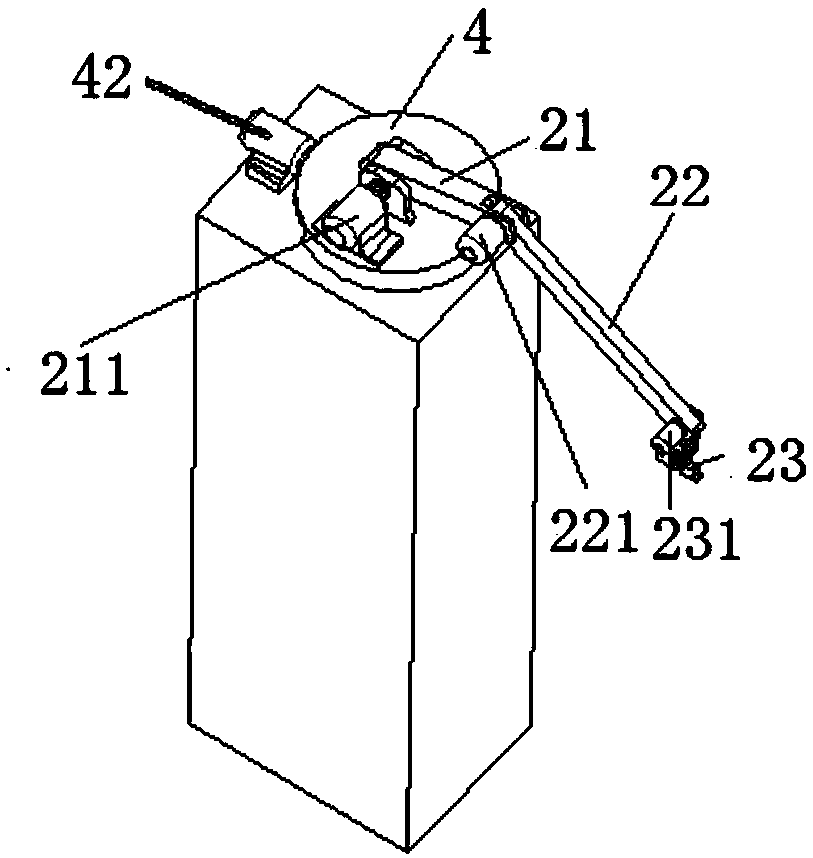
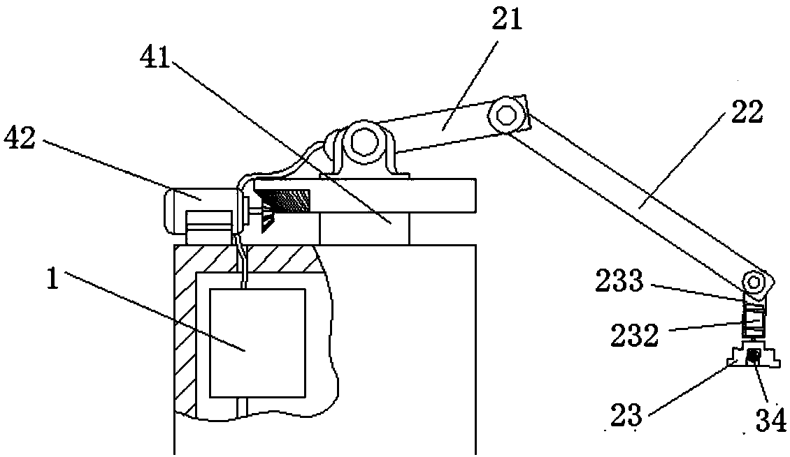
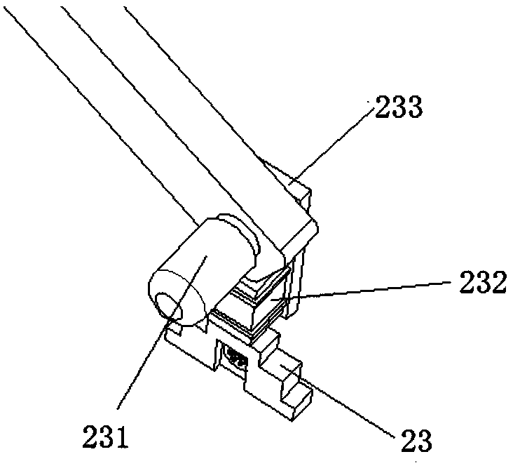
[0043] like Figure 1-5As shown, an electric bus charging automatic guidance device includes a controller 1 with a wireless module, an adjustment mechanism 2, a positioning mechanism 3 and a display module 6, and the adjustment mechanism 2 includes a first arm 21, a second arm 22 and a charging interface 23, the first arm 21 is fixed on the turntable 4, the turntable 4 rotates around the turntable shaft 41, the first arm servo motor 211 controls the movement of the first arm 21, the second arm servo motor 221 is fixed to the first arm 21, and the second arm servo motor 221 controls the movement of the second arm 22, the second arm 22 is fixed to the interface servo motor 231, the axis of the interface servo motor 231 is connected to the connecting piece 233, the charging interface 23 is connected to the interface rotating motor 232, and the interface rotating motor 232 is fixed to the connecting piece 233; The interface 13 is provided with a positioning mechanism 3, including ...
Embodiment 2
[0063] The difference between this embodiment and Embodiment 1 is that multiple charging interfaces are provided, and the multiple charging interfaces are connected in series. like Figure 9-11 As shown, the charging interface 23 is provided with a first charging interface 234, a second charging interface 235 and a third charging interface 236, and the first charging interface 234, the second charging interface 235 and the third charging interface 236 are connected in sequence.
[0064] The upper end of the second charging interface 235 is provided with a vertical ultrasonic probe 313, one side of the first charging interface 234 is provided with a first horizontal ultrasonic probe 311, and one side of the third charging interface 236 is provided with a second horizontal ultrasonic probe 312. The motor 333 drives the vertical ultrasonic probe 313 to rotate, the first horizontal stepping motor 331 drives the first horizontal ultrasonic probe 311 to rotate, and the second horizo...
Embodiment 3
[0066] Both the adjusting mechanism and the positioning mechanism in this embodiment are arranged on the moving mechanism. The motion control model of the adjustment mechanism, the principle of positioning the ultrasonic probe in the vertical direction, and the principle of positioning the ultrasonic probe in the horizontal direction in this embodiment are the same as those in Embodiment 1.
[0067] like Figure 12-17 As shown, the moving mechanism 5 includes a sliding platform 51 , a synchronous belt 52 , and a sliding platform guide rail 53 fixed on the platform, and the first arm 21 and the first arm servo motor 211 are fixed on the sliding platform 51 . The synchronous belt 52 includes an upper belt 521 and a lower belt 522. The upper belt 521 is connected to the sliding table 51, and the lower belt 522 passes through the sliding table 51. The synchronous belt 52 drives the sliding table 51 to move along the sliding table guide rail 53, and the sliding table 51 slides forw...
PUM
 Abstract
Description
Claims
Application Information
 - R&D
- Intellectual Property
- Life Sciences
- Materials
- Tech Scout
- Unparalleled Data Quality
- Higher Quality Content
- 60% Fewer Hallucinations
Browse by: Latest US Patents, China's latest patents, Technical Efficacy Thesaurus, Application Domain, Technology Topic, Popular Technical Reports.
© 2025 PatSnap. All rights reserved.Legal|Privacy policy|Modern Slavery Act Transparency Statement|Sitemap|About US| Contact US: help@patsnap.com


