Engine intake pipe

A technology for intake pipes and engines, which is applied in the direction of engine components, machines/engines, mechanical equipment, etc., can solve the problems of no filtered gas in the intake pipe, insufficient firmness of the intake pipe, interference with cab members, etc., to protect the engine, facilitate disassembly and Good effect of replacement and pressure resistance

Inactive Publication Date: 2018-09-28
南京世界村汽车动力有限公司
View PDF8 Cites 4 Cited by
  • Summary
  • Abstract
  • Description
  • Claims
  • Application Information

AI Technical Summary

Problems solved by technology

[0002] The intake pipe is an important part of the intake and exhaust system of the engine. Its design has a certain impact on the performance of the engine. The existing intake pipe itself has no function of filtering gas. The air generally passes through the intake pipe first and then passes through the air filter. After a long period of use, the body is prone to deposit dust inside, and even cause blockage, and in the prior art, the air intake system of the car is generally arranged in the engine room, and the intake air caused by the periodic opening and closing of the engine intake valve is affected when the airflow enters. The pressure in the pipe fluctuates to form a pulsating noise, and the noise will radiate outward through the airflow resonance, disturbing the members of the cab. At the same time, the existing air intake pipe is not strong enough to withstand the airflow pressure for a long time and is easy to be damaged. Therefore, the present invention proposes an engine Air intake pipe to solve the problems existing in the prior art

Method used


Image

  • Engine intake pipe
  • Engine intake pipe
  • Engine intake pipe

Examples


Embodiment Construction

[0016] In order to deepen the understanding of the present invention, the present invention will be further described below in conjunction with the examples, which are only used to explain the present invention, and do not constitute a limitation to the protection scope of the present invention.

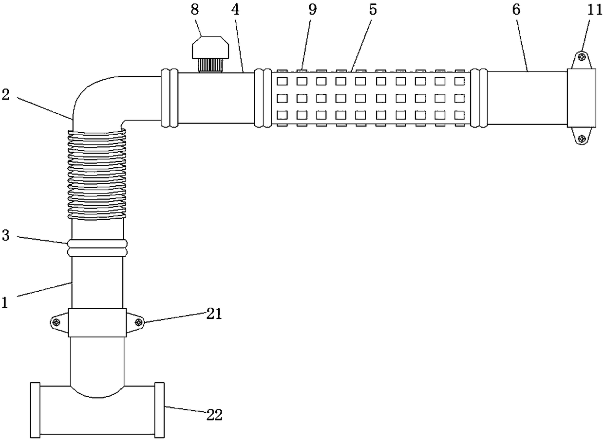
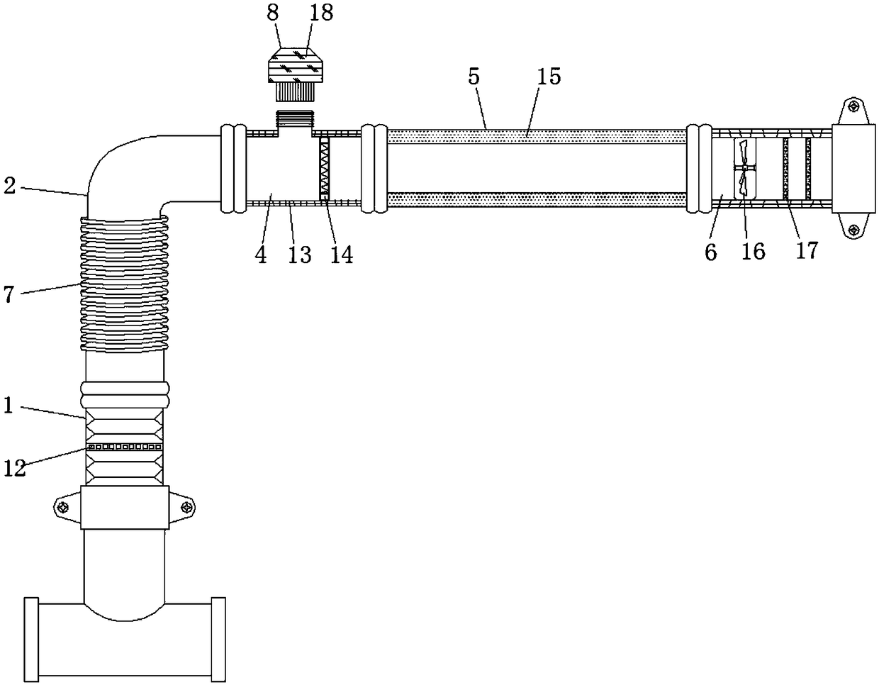
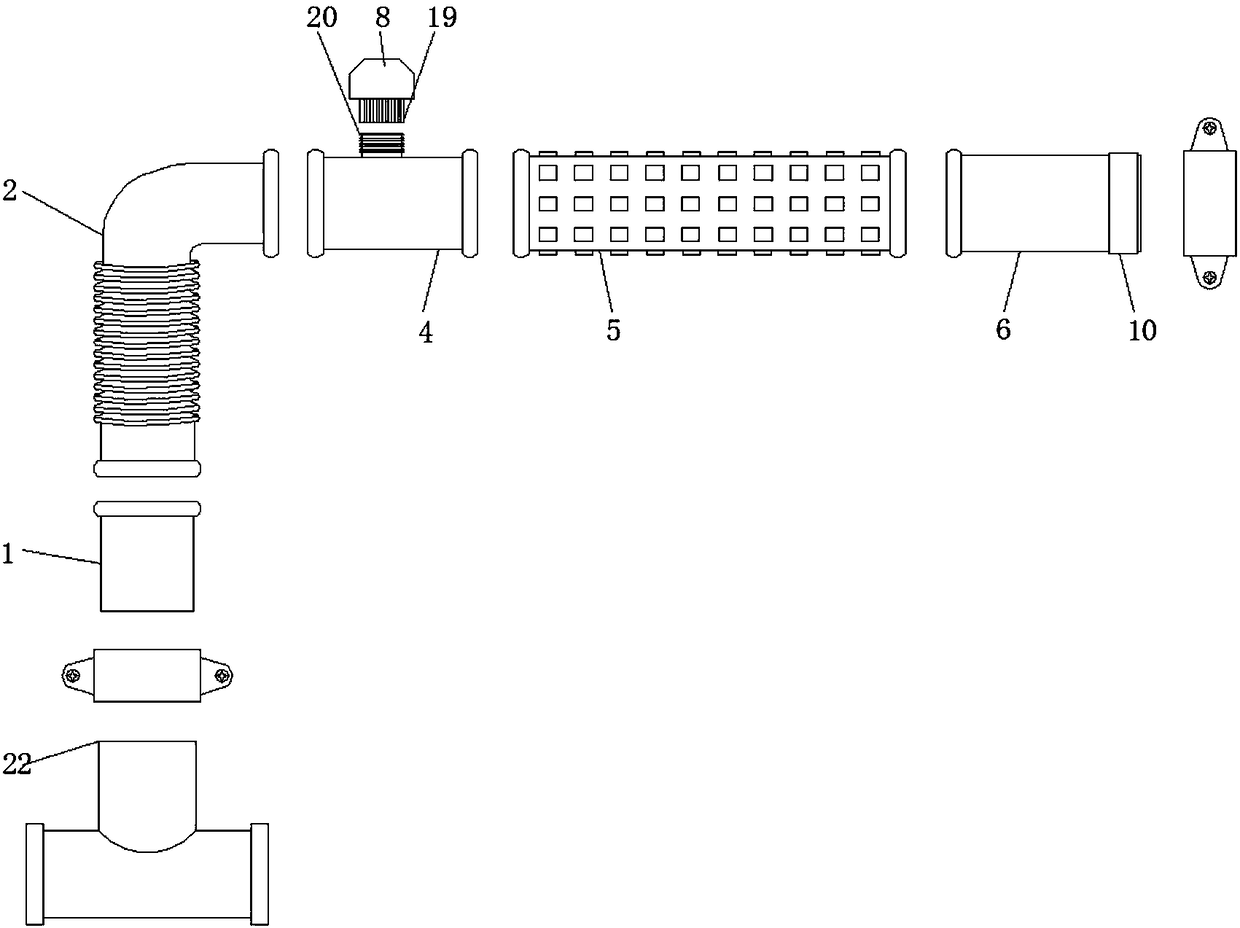
[0017] according to figure 1 , 2 , 3, the present embodiment provides an engine intake pipe, including a dehumidification pipe 1, a telescopic pipe 2, a flange 3, a filter pipe 4, a muffler pipe 5 and a uniform flow pipe 6, and the top of the dehumidification pipe 1 is installed There is a telescopic pipe 2, and a flange 3 is provided between the dehumidification pipe 1 and the telescopic pipe 2, the dehumidification pipe 1 and the telescopic pipe 2 are installed through the flange 3, and the end of the telescopic pipe 2 away from the dehumidification pipe 1 passes through the flange 3 is equipped with a filter pipe 4, and the end of the filter pipe 4 away from the telescopic pipe 2...


PUM


Abstract

The invention discloses an engine intake pipe. The engine intake pipe comprises a dehumidifying pipe, a telescopic pipe, flanges, a filter pipe, a silencing pipe and a flow uniformizing pipe. The telescopic pipe is mounted on the upper portion of the dehumidifying pipe. The corresponding flange is arranged between the dehumidifying pipe and the telescopic pipe. The dehumidifying pipe and the telescopic pipe are mounted through the corresponding flange. The filter pipe is mounted at the end, away from the dehumidifying pipe, of the telescopic pipe through the corresponding flange. The silencingpipe is mounted at the end, away from the telescopic pipe, of the filter pipe through the corresponding flange. The flow uniformizing pipe is mounted at the end, away from the filter pipe, of the silencing pipe through the corresponding flange. The telescopic pipe is of a bent structure. One section of the telescopic pipe is arranged as a folding pipe. An adsorption box is arranged at one end ofthe top of the filter pipe. Airflow can be filtered through the filter pipe, dust is filtered off and adsorbed by the adsorption box, impulsive noise generated by airflow during passing can be effectively absorbed through the silencing pipe, and a member in a cab is prevented from being disturbed.

Description

technical field [0001] The invention relates to the technical field of auto parts, in particular to an engine intake pipe. Background technique [0002] The intake pipe is an important part of the intake and exhaust system of the engine. Its design has a certain impact on the performance of the engine. The existing intake pipe itself has no function of filtering gas. The air generally passes through the intake pipe first and then passes through the air filter. After a long period of use, the body is prone to deposit dust inside, and even cause blockage, and in the prior art, the air intake system of the car is generally arranged in the engine room, and the intake air caused by the periodic opening and closing of the engine intake valve is affected when the airflow enters. The pressure in the pipe fluctuates to form a pulsating noise, and the noise will radiate outward through the airflow resonance, disturbing the members of the cab. At the same time, the existing air intake ...

Claims


Application Information

Patent Timeline
Patent Type & Authority Applications(China)
IPC IPC(8): F02M35/104F02M35/14
CPCF02M35/104F02M35/14
Inventor 孙兰娟李健
Owner 南京世界村汽车动力有限公司
Why Eureka
Try Eureka