
an isostatic press

A technology of isostatic presses and racks, applied in mechanical equipment, fluid pressure actuation devices, fluid pressure actuation system components, etc., can solve the problem of easily damaged components such as hydraulic valves, damage to pressurized cylinders, and safety accidents and other problems, to achieve the effect of reducing processing difficulty, reliable sealing, and convenient adjustment

Active Publication Date: 2019-01-25
四川力能超高压设备有限公司
View PDF7 Cites 0 Cited by
  • Summary
  • Abstract
  • Description
  • Claims
  • Application Information

AI Technical Summary

Problems solved by technology

However, as the length of the workpiece to be formed becomes longer and longer, the length of the working chamber also increases. Therefore, a positioning device must be added to ensure the relative position between the working chamber and the pressure head, so as to prevent the piston rod of the booster cylinder from driving the pressure head to work deeply. When the cavity is blocked by the working cavity, it will cause damage to the pressurized cylinder and even cause a safety accident
In addition, because the pressure of the liquid in the working chamber is very high, between 400MPa and 600MPa, when the booster cylinder returns, that is, when the piston rod of the booster cylinder is retracted, it is easy to damage the hydraulic valve and other components in the hydraulic control system.

Method used


Image

  • an isostatic press
  • an isostatic press
  • an isostatic press

Examples


Embodiment Construction

[0033] The present invention will be further elaborated below in conjunction with the accompanying drawings and specific embodiments.

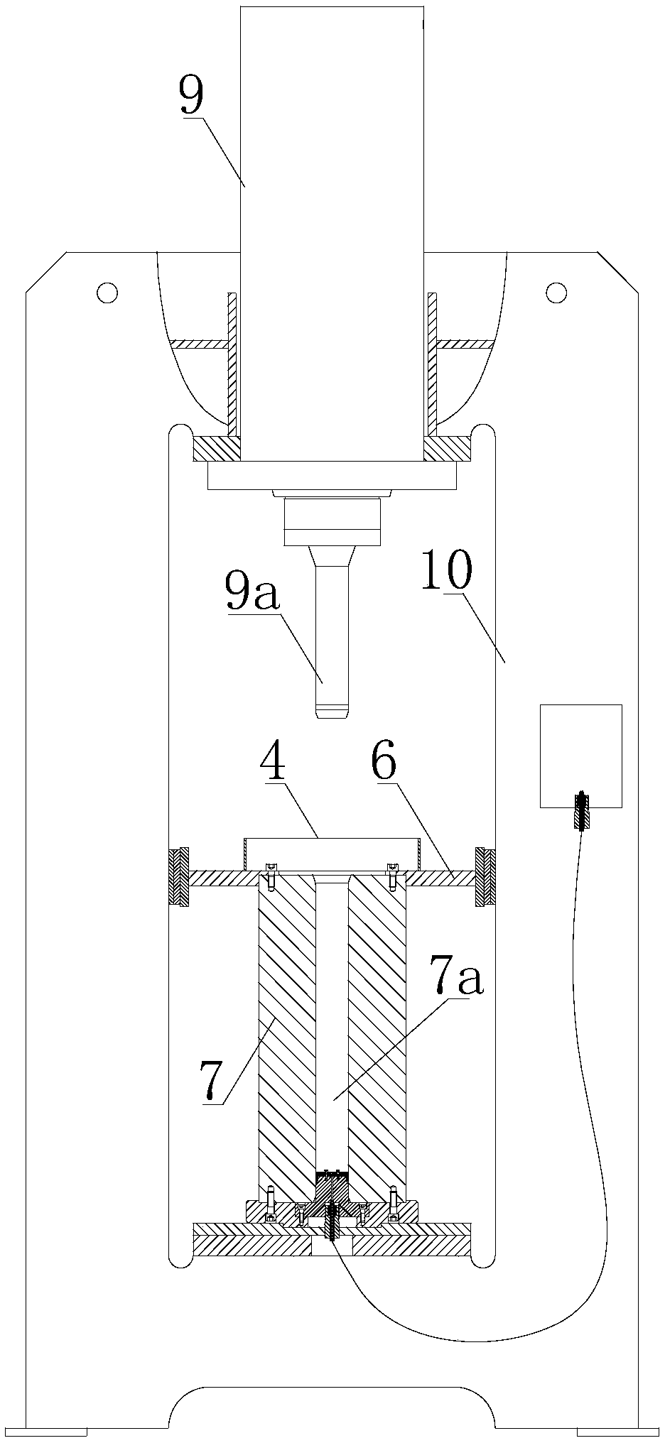
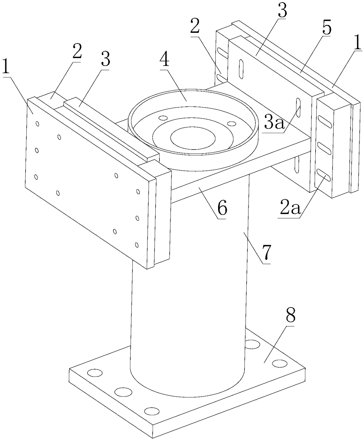
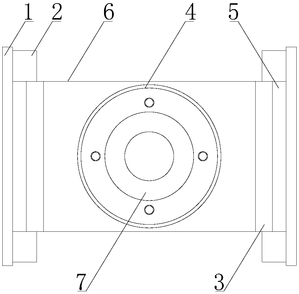
[0034] like Figure 1-9 As shown, a kind of isostatic press of the present embodiment comprises a frame 10, a booster cylinder 9 fixedly arranged at the top of the frame 10, a working cylinder fixedly arranged at the bottom of the frame 10, and a working cylinder fixedly arranged at the top of the frame 10. The pressure head 9a on the piston rod of the booster cylinder 9; the working cylinder is provided with a working chamber 7a; it also includes a positioning device and a hydraulic control system for controlling the action of the booster cylinder 9;

[0035] The positioning device includes an adjustment assembly and a working cylinder positioning plate 6; the bottom end surface of the working cylinder positioning plate 6 is provided with a positioning stop for positioning the working cylinder; the working cylinder positioning plate 6 and the...


PUM


Abstract

The invention belongs to the technical field of isostatic pressing treatment and discloses an isostatic pressing machine. The isostatic pressing machine comprises a rack, a pressure cylinder fixedly arranged on the top of the rack, a working cylinder fixedly arranged at the bottom of the rack and a pressure head fixedly arranged on a piston rod of the pressure cylinder. The working cylinder is internally provided with a working cavity. The isostatic pressing machine further comprises a locating device and a hydraulic control system for controlling the pressure cylinder to act. An adjusting assembly and a working cylinder locating plate are arranged to guarantee the relative positions of the working cavity and the pressure head so as to guide the pressure head, and then the pressure head and the pressure cylinder are protected; secondly, a pressure relief oil circuit is arranged to relieve the pressure of a rodless cavity of the pressure cylinder when the piston rod of the pressure cylinder drives the pressure head to return; after the hydraulic pressure in the working cavity drops, the isostatic pressing machine is switched from the pressure relief oil circuit to a main oil circuit, so that components such as a hydraulic valve in the hydraulic control system are protected against damage.

Description

technical field [0001] The invention belongs to the technical field of isostatic pressing treatment equipment, and in particular relates to an isostatic pressing machine. Background technique [0002] Isostatic pressing is to place the workpiece to be processed in a specific mold, then put the mold with the workpiece into the working cylinder filled with liquid, and drive the pressure head deep into the working cylinder through the piston rod of the booster cylinder The working chamber of the machine is gradually pressurized, and the pressure is transmitted through the liquid, so that all surfaces of the object are subjected to equal pressure, and are formed under the limitation of the mold. Due to the short working chamber in the working cylinder of the existing isostatic press and the short stroke of the booster cylinder, the equipment can work normally even without a positioning device. However, as the length of the workpiece to be formed becomes longer and longer, the l...

Claims


Application Information

Patent Timeline
Patent Type & Authority Patents(China)
IPC IPC(8): F15B11/042F15B13/02F15B19/00F15B21/00
CPCF15B11/042F15B13/02F15B13/027F15B19/00F15B21/00
Inventor 孙贵忠高潮涌
Owner 四川力能超高压设备有限公司
Learn More