A hydraulic valve for agricultural machinery

A technology of hydraulic valves and agricultural machinery, applied in the field of hydraulic valves, can solve the problems of high cost, poor reliability, complex structure, etc., and achieve the effect of low cost, few parts and high degree of automation

Active Publication Date: 2020-09-25
兀结石
View PDF7 Cites 0 Cited by
  • Summary
  • Abstract
  • Description
  • Claims
  • Application Information

AI Technical Summary

Problems solved by technology

However, the structure is very complicated, the reliability is poor, and the cost of two control rotary valves is still high

Method used


Image

  • A hydraulic valve for agricultural machinery
  • A hydraulic valve for agricultural machinery
  • A hydraulic valve for agricultural machinery

Examples


Embodiment Construction

[0017] The present invention will be further described in detail below in conjunction with the accompanying drawings and embodiments.

[0018] Such as Figure 1~3 Shown is a preferred embodiment of the present invention.

[0019] A hydraulic valve for agricultural machinery comprising:

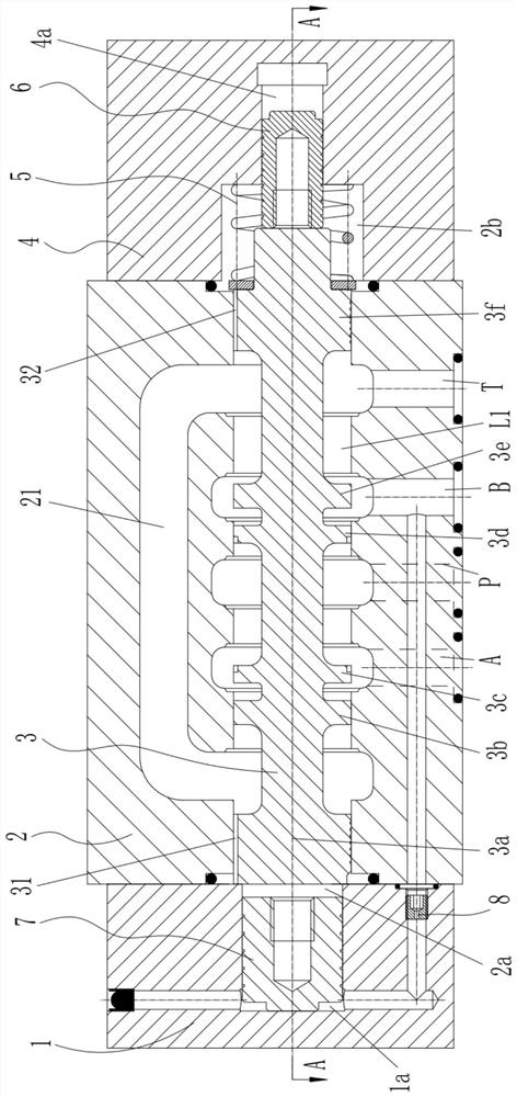
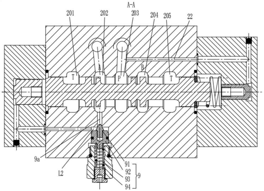
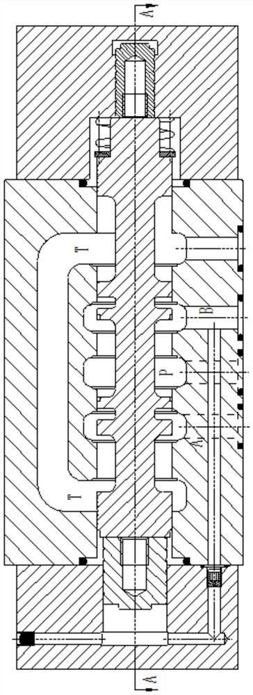
[0020] Valve block 2, valve block 2 is provided with oil inlet P, oil return port T, first working oil port A and second working oil port B;

[0021] The first channel L1, the first channel L1 has annular first flow groove 201, second flow groove 202, third flow groove 203, fourth flow groove 204 and fifth flow groove 205, valve block 2 is also provided with a first flow channel 21 for connecting the first flow groove 201 and the fifth flow groove 205, the second flow groove 202 is connected with the first working oil port A, and the third flow groove 203 is connected with the inlet port A. The oil port P is connected, the fourth flow groove 204 is connected with the second working oil port...


PUM


Abstract

The invention relates to a hydraulic valve for an agricultural machine. The hydraulic valve for the agricultural machine is characterized by comprising a valve block, a reversing valve core, a left end cover, a right end cover, a large plunger piston, a small plunger piston, a first spring and an overflow valve; an oil inlet, an oil returning port, a first working oil port and a second working oilport are formed in the valve block; a first channel and a second channel are formed in the valve block; the reversing valve core is arranged in the first channel in a sliding manner; the left end cover and the right end cover are respectively fixed to the left end and the right end of the valve block and are used for plugging the first channel; the large plunger piston is arranged in the left endcover in the sliding manner and forms a main control cavity with the left end cover; the small plunger piston is arranged in the right end cover in the sliding manner and forms a left control cavitywith the right end cover; the first spring is arranged in a right oil returning cavity; the overflow valve is arranged on the second channel for normally disconnecting the second channel; and the reversing valve core can be switched between a left end position and a right end position. The hydraulic valve for the agricultural machine is simple in structure and low in manufacturing cost, and can realize automatic control.

Description

technical field [0001] The invention belongs to the technical field of hydraulic valves, in particular to a hydraulic valve for agricultural machinery. Background technique [0002] In recent years, most areas of my country have begun to promote the application of hydraulic turning plows. Using the reversing plow for plowing has the advantages of no opening and closing ridges, high production efficiency, and energy saving. The hydraulic reversing plow uses the hydraulic system of the tractor to control the left and right plow bodies to operate alternately, so as to achieve the purpose of no opening and closing ridges. Such as Figure 6 As shown, the turning mechanism of the hydraulic turning plow mainly includes a suspension frame 101, a rotating shaft 105, a plow beam 102 and an oil cylinder 103. The rotating shaft 105 is welded on the suspension frame 101, and the plow beam 102 is installed on the rotating shaft 105. Hinged on the suspension frame top and the plow beam 1...

Claims


Application Information

Patent Timeline
Patent Type & Authority Patents(China)
IPC IPC(8): F15B13/042F16K11/07A01B15/00
CPCA01B15/00F15B13/0402F15B2013/041F16K11/07
Inventor 邵立坤
Owner 兀结石
Why Eureka
Try Eureka