Automatic water draining tee joint device

A three-way device, automatic technology, applied in the direction of the valve device, multi-way valve, passing components, etc., can solve the problems of increasing the power of the cooling system of the machine, not being able to be used well, and the joints can not be well connected to external applications, etc., to achieve a simple structure , safe to use, conducive to the promotion of the effect of the application

Inactive Publication Date: 2018-09-28
SHANGHAI APOLO MEDICAL TECH CO LTD
View PDF6 Cites 0 Cited by
  • Summary
  • Abstract
  • Description
  • Claims
  • Application Information

AI Technical Summary

Problems solved by technology

Laser treatment equipment or other treatment equipment in the beauty and medical industry requires a three-way device to be used in the heat dissipation system to facilitate heat dissipation and cooling for the machine and increase the cooling system power of the machine. The traditional shower faucet three-way is to press a button For water switching, the joints cannot be used for external connection, and the external refrigeration equipment cannot be expanded, so it cannot be well applied in the heat dissipation circulation system of the machine

Method used


Image

  • Automatic water draining tee joint device
  • Automatic water draining tee joint device
  • Automatic water draining tee joint device

Examples


Embodiment

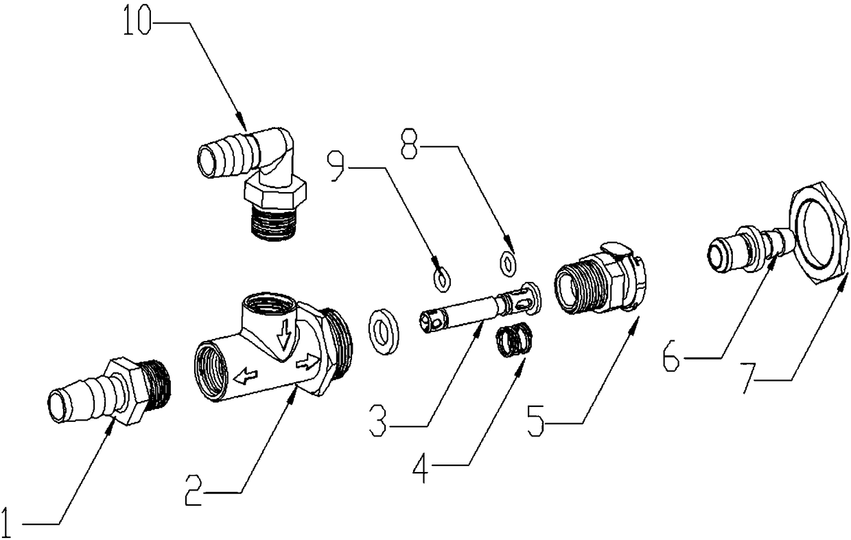
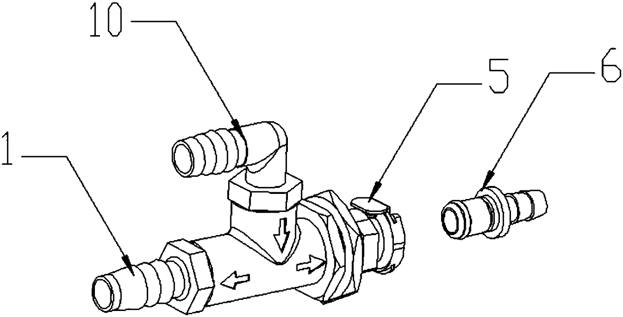
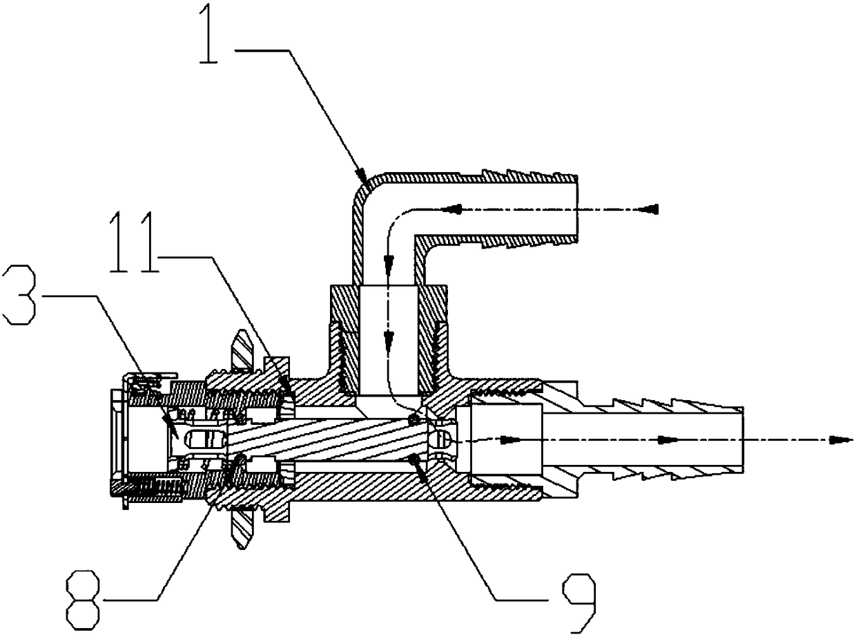
[0028] Example: such as Figure 1-4 As shown, the present invention provides an automatic water-cutting tee device, which includes a second faucet 1, a tee main body 2, a water-cutting rod fixing seat 5 and a fixing nut 7 connected by threads in turn, and the three-way main body 2 is respectively There are B ports and C ports located at both ends of the main body and A port arranged on the upper part of the three-way main body 2. The A port of the three-way main body 2 is threadedly connected with the second faucet 1, and the C port of the three-way main body 2 is provided with The movable water cutting rod 3 is equipped with a return spring 4 to control its reciprocating movement, and the two ends of the movable water cutting rod 3 are provided with water outlet sealing rings, which are the second water outlets at the left end of the movable water cutting rod 3 respectively. The sealing ring 9 and the first water outlet sealing ring 8 at the right end, the tail end of the mov...


PUM


Abstract

The invention discloses an automatic water draining tee joint device. The automatic water draining tee joint device comprises a second water nozzle, a tee joint body, a water draining rod fixing seatand a fixing nut which are connected through threads in sequence. The tee joint body is provided with a port B, a port C and a port A arranged on the upper portion of the tee joint body, and the portB and the port C are located at the two ends of the tee joint body. The port A of the tee joint body is in threaded connection with the second water nozzle. A movable water draining rod is arranged inthe port C of the tee joint body. A reset spring controlling the movable water draining rod to do reciprocating motion is arranged on the movable water draining rod. The two ends of the movable waterdraining rod are both provided with water outlet seal rings including the second water outlet seal ring located at the left end of the movable water draining rod and the first water outlet seal ringlocated at the right end of the movable water draining rod. The tail end of the movable water draining rod is sleeved with the water draining rod fixing seat. A third water nozzle is connected to theupper end of the water draining rod fixing seat through the fixing nut. The automatic water draining tee joint device is provided with the automatic water draining rod and other devices, is applied toa laser therapeutic instrument cooling system, facilitates expansion and external connection of an instrument with refrigerating equipment and improves the heat dissipating capability to the equipment.

Description

technical field [0001] The invention belongs to the technical field of laser treatment instruments, and in particular relates to an automatic water cutting three-way device. technical background [0002] Tees, also known as pipe fittings tees or tee fittings, tee joints, etc., are mainly used to change the direction of the fluid. They are used at the branch pipes of the main pipeline and can be classified according to the size of the pipe diameter. Generally made of carbon steel, cast steel, alloy steel, stainless steel, copper, aluminum alloy, plastic, PVC and other materials. There are many types of water cutting tees, such as ordinary tees, manual switching tees, electric tees and other types. Laser treatment equipment or other treatment equipment in the beauty and medical industry requires a three-way device to be used in the heat dissipation system to facilitate heat dissipation and cooling for the machine and increase the cooling system power of the machine. The tradi...

Claims


Application Information

Patent Timeline
Patent Type & Authority Applications(China)
IPC IPC(8): F16K11/044F16L15/04
CPCF16K11/044F16L15/008
Inventor 邱秋林高剑
Owner SHANGHAI APOLO MEDICAL TECH CO LTD
Why Eureka
Try Eureka