Ultralow-temperature condensation enrichment system
An ultra-low temperature and enrichment technology, applied in the direction of refrigerators, refrigeration components, refrigeration and liquefaction, etc., can solve the problems of large cooling loss and large volume, and achieve the effect of reducing volume, reducing volume and reducing heat capacity
- Summary
- Abstract
- Description
- Claims
- Application Information
AI Technical Summary
Problems solved by technology
Method used
Image

Examples
Embodiment 1
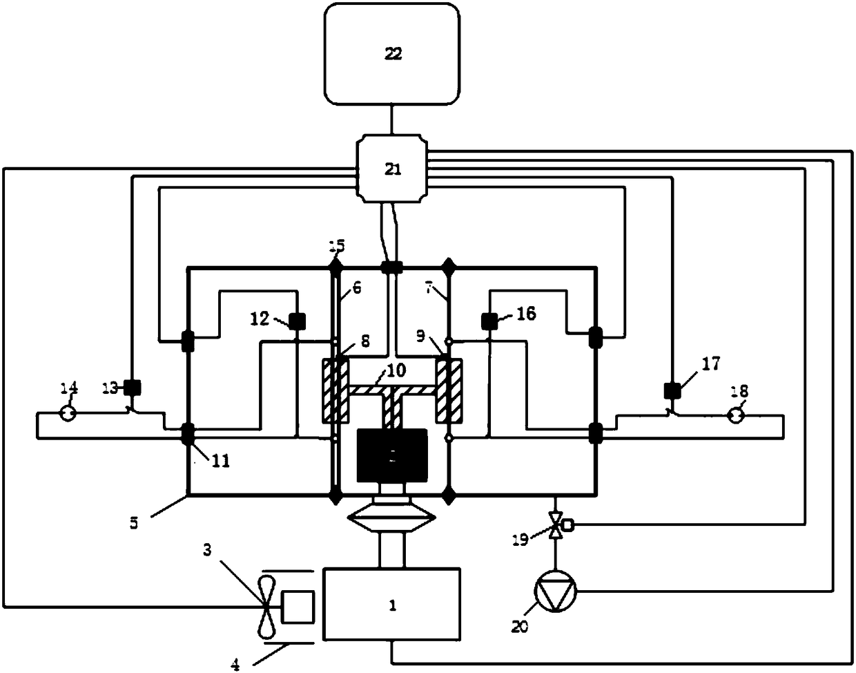
[0069] Such as Figure 1-6 As shown, a kind of ultra-low temperature condensation enrichment system of the present invention comprises:
[0070] The water removal pipeline system includes a water removal pipe 6 and a water removal pipe heating device, wherein the water removal pipe 6 includes a first pipeline layer 300, a second pipeline layer 301 arranged on the outside of the first pipeline layer 300, the The second pipeline layer 301 is used to transfer cold energy to the first pipeline layer 300 to refrigerate the first pipeline layer 300 so that the sampled gas passing through the first pipeline layer 300 The water vapor condenses on the inner wall of the first pipeline layer 300 to realize water removal from the sampled gas, and the water removal pipe heating device is used to heat the first pipeline layer 300 to condense on the first pipeline layer The water vapor within 300 is evaporated to realize the drying of the water removal pipe 6;
[0071] The enrichment analy...
Embodiment 2
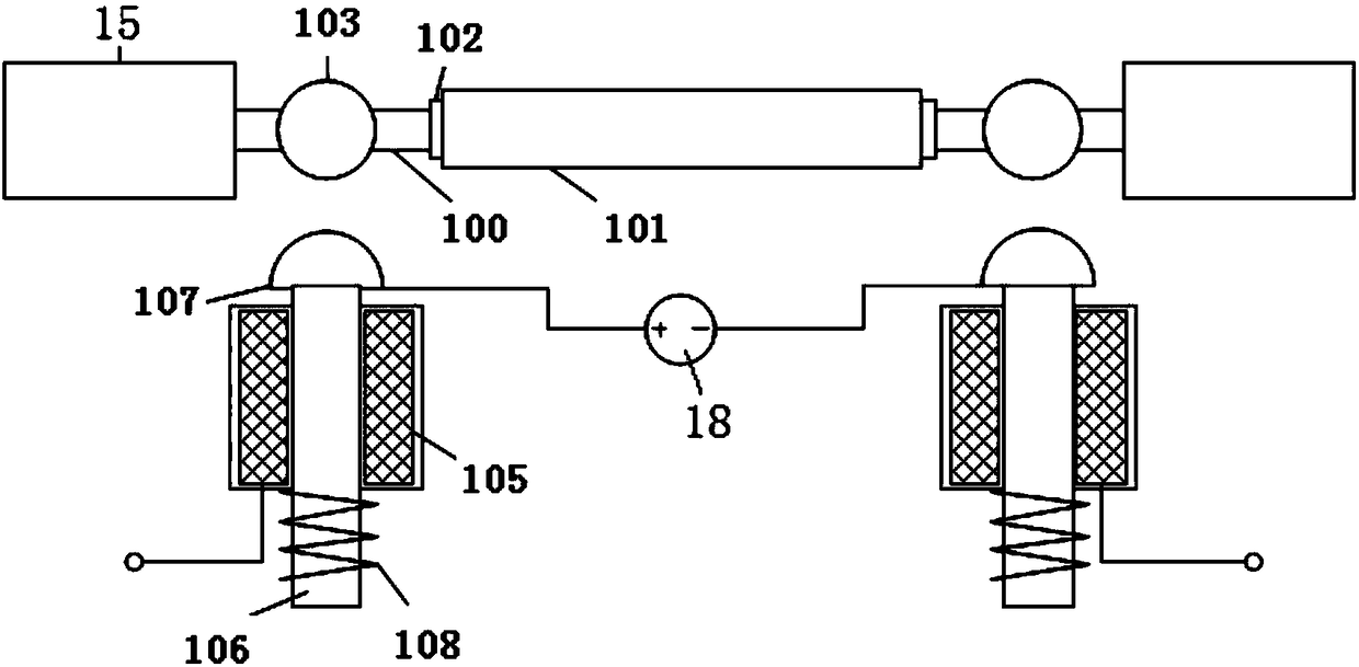
[0092] Due to the different cooling temperatures of the enrichment and desorption pipe 7 and the water removal pipe 6, the enrichment and desorption pipe 7 generally needs to be around -150°C, while the temperature of the water removal pipe 6 needs to be around -50°C. cold source of temperature. In order to further reduce the space occupied by the ultra-low temperature condensation enrichment system and reduce energy consumption, the cold source providing device of the present invention adopts a special structure. The structure of the cold source providing device is introduced in detail below:
[0093] Such as Figure 7 and 8 As shown, the cold source providing device of the present invention includes a refrigeration system 1 and a cold source distribution system 10;
[0094] The refrigeration cold head 2 of the refrigeration system 1 is suitable for connecting with the fourth pipeline layer 101 to provide cooling capacity for the fourth pipeline layer 101; the cold source d...
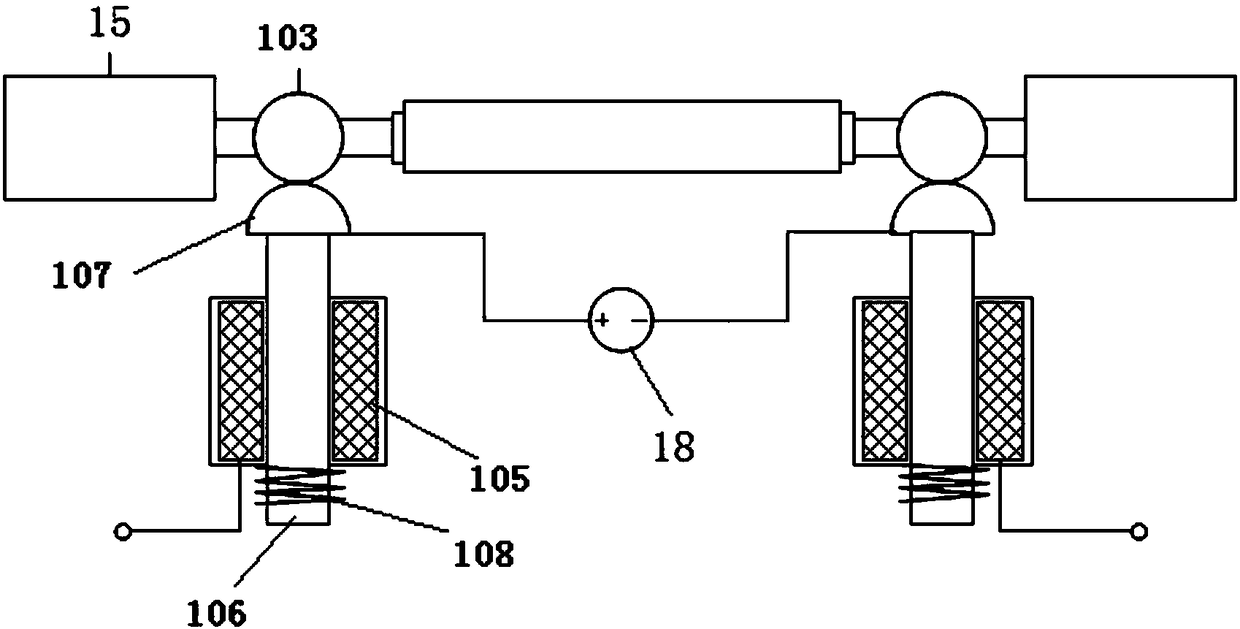
Embodiment 3
[0100] The difference between Embodiment 3 and Embodiment 2 is that the heat conduction structure further includes a heat conduction bracket 205, one end of the heat conduction bracket 205 is connected to the heat conduction ring 204, and the other end is connected to the auxiliary cold head 206, and the The cold head 206 is adapted to be connected with the second pipeline layer 301 .
[0101] The heat conduction structure includes a thermal resistance mechanism 210 , one end of the thermal resistance mechanism 210 is connected to the cooling head 2 , and the other end is connected to the second pipeline layer 301 .
[0102]Since the thermal resistance mechanism 210 has thermal resistance, the temperature of the cold energy transferred from the thermal resistance mechanism 210 to the second pipeline layer 301 is higher than that of the cooling head 202 to the fourth pipeline layer. 101 The temperature of the cooling capacity provided.
PUM
 Abstract
Description
Claims
Application Information