
Fitting assembly for hood and projectile body

A projectile and assembly technology, which is applied in the field of hood and projectile assembly assembly, can solve problems such as poor closing pressure consistency, low shift output, and high labor intensity, and achieve lower production environment requirements, wide application range, The effect of improving safety

Pending Publication Date: 2018-09-28
ANHUI FANGYUAN MECHANICAL & ELECTRICAL
View PDF0 Cites 3 Cited by
  • Summary
  • Abstract
  • Description
  • Claims
  • Application Information

AI Technical Summary

Problems solved by technology

And most of the existing hood and body are threaded connection
But for some specific types of bombs, since the upper and lower parts of the bombs are connected by wires, if the existing spiral method is still used to connect the hood and the body, it will inevitably affect or even damage the wires.
[0003] Moreover, most of the existing closing machines are hand pull presses, which have a low degree of mechanization and rely entirely on manpower to pull the turntable and the handle for multiple times of continuous pressurization. The closing pressure consistency is poor, and multiple operators are required for closing at the same time. Large, low shift output and low efficiency
For a certain automatic mouth closing machine, the degree of mechanization is high, there are many circuit devices and sensing elements, and the operation can be completed by a single person, and the working time is about 90 rounds / h, but the purchase price is expensive, the debugging is difficult, and the equipment is bulky , cannot be moved flexibly, and professionals are required to maintain in the follow-up, the maintenance cost is high, and the equipment consumes a lot of electricity. If it is used in the ammunition production workshop, it needs a higher safety guarantee, which greatly increases the ammunition production. cost and production risk

Method used


Image

  • Fitting assembly for hood and projectile body
  • Fitting assembly for hood and projectile body

Examples


Embodiment Construction

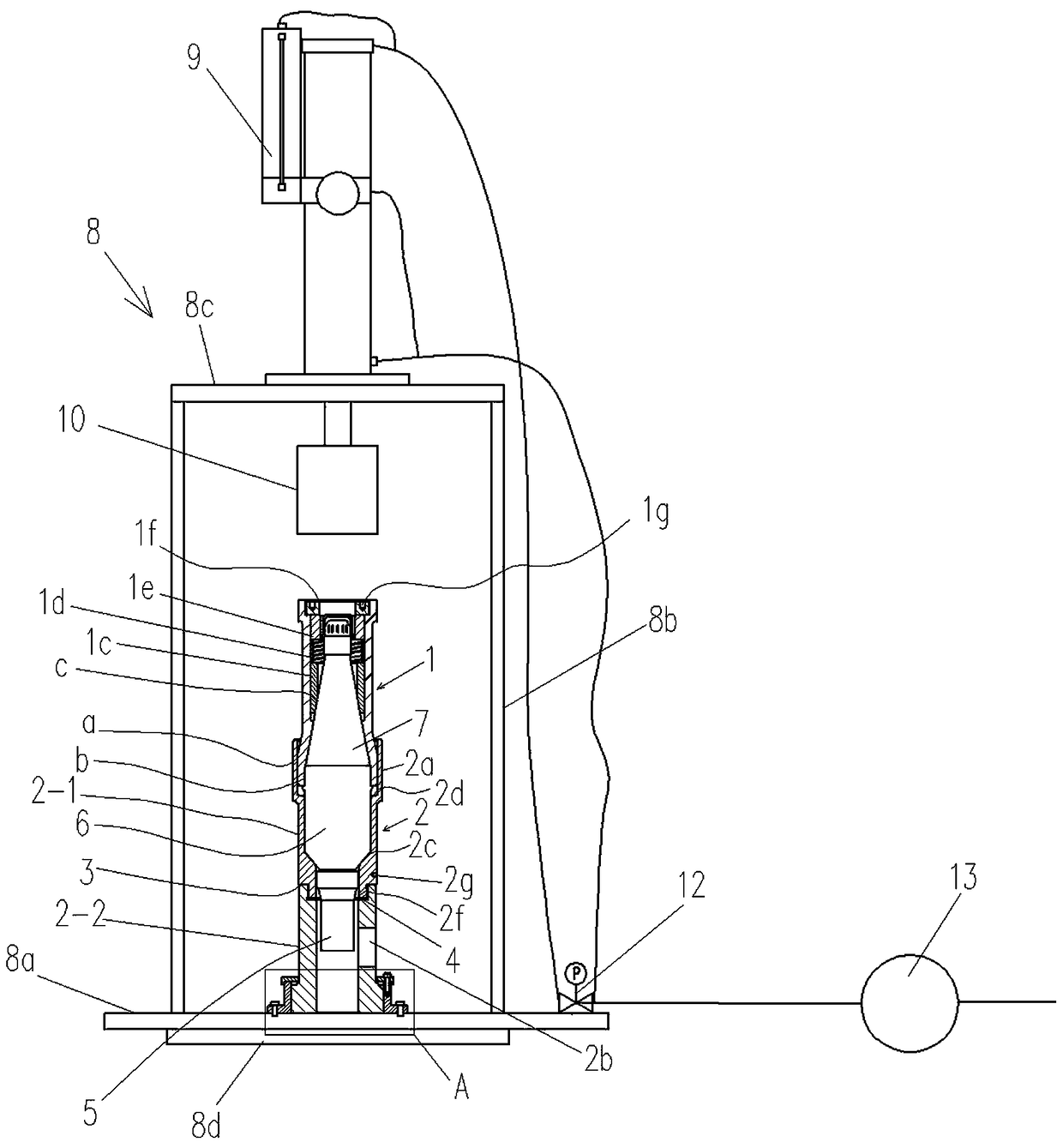
[0015] Such as figure 1 As shown, an assembly assembly for the wind cap and the projectile body, which includes a press device and a corresponding closing device, the press device includes a frame 8, and the frame 8 includes a lower working Table 8a is provided with a group of columns 8b on the lower table 8a, an upper table 8c is provided at the top of the column 8b, and a reinforcing plate 8d is also provided on the back side of the lower table 8a.

[0016] A gas-liquid booster cylinder 9 is arranged on the upper workbench 8c, the lower end of the output shaft of the gas-liquid booster cylinder 9 is located below the upper workbench 8c, and a pressure head 10 is arranged at the lower end of the output shaft. A slot 11 corresponding to the indenter 10 is provided on the lower workbench 8 a below the indenter 10 .

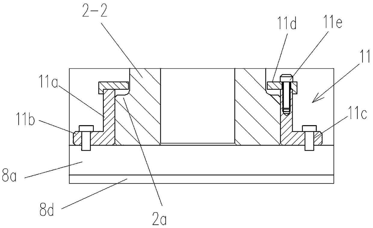
[0017] Such as figure 2 As shown, the clamping groove 11 includes an arc-shaped groove 11 a arranged coaxially with the indenter 10 . An outwardly extending fl...


PUM


Abstract

The invention provides a fitting assembly for a hood and a projectile body. The fitting assembly is characterized in that the fitting assembly comprises a press machine device and a necking-in devicecorrespondingly matched with the press machine device, the press machine device comprises a machine frame (8) and an air-liquid supercharging cylinder (9), a pressure head (10) is arranged on an output shaft of the air-liquid supercharging cylinder (9), the machine frame (8) is provided with a clamping groove (11) corresponding to the pressure head (10) and a control valve (12) connected and matched with the air-liquid supercharging cylinder (9), and the control valve (12) communicates with an air source through a pressure control valve (13); and the necking-in device comprises an upper die-sleeve (1) and a lower die-sleeve (2) which are coaxially matched, and an expanding portion (2a) correspondingly matched with the clamping groove (11) is arranged at the outer wall of the lower end portion of the lower die-sleeve (2). The fitting assembly has the advantages of being simple in structure, easy to operate, high in safety, low in cost, wide in application, and low in follow-up maintenance expense.

Description

Technical field: [0001] The invention relates to the field of ammunition assembly, in particular to an assembly assembly for a wind cap and an ammunition body. Background technique: [0002] In the assembly process of military products, the sealing technology of the hood and the projectile is used to increase the connection strength between the projectile and the hood, and at the same time plays an important role in the airtightness, stability and aesthetics of the projectile. And most of the existing hood and the body are threaded. But for some specific types of bombs, since the upper and lower parts of the bombs are connected by wires, if the existing spiral mode is still used to connect the hood and the body, it will inevitably affect or even damage the wires. [0003] Moreover, most of the existing closing machines are hand pull presses, which have a low degree of mechanization and rely entirely on manpower to pull the turntable and the handle for multiple times of cont...

Claims


Application Information

Patent Timeline
Patent Type & Authority Applications(China)
IPC IPC(8): F42B33/02B21D39/00
CPCF42B33/025B21D39/00
Inventor 朱安徽李道全刘明志周良郑自清周志强李道政
Owner ANHUI FANGYUAN MECHANICAL & ELECTRICAL
Learn More