Measuring device for D type auxiliary girder displacement and bridge pier inclination angle and measuring method thereof
A measuring device and dislocation technology, which is applied in the direction of measuring devices, electrical devices, and measuring inclination, can solve the problems of easy misalignment and poor integrity of adjacent longitudinal beams, and achieve the reduction of the number of layouts, and the improvement of precision and efficiency high effect
- Summary
- Abstract
- Description
- Claims
- Application Information
AI Technical Summary
Problems solved by technology
Method used
Image
Examples
Embodiment 1
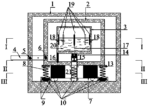
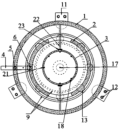
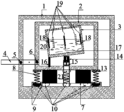
[0026] A measuring device for D-type beam dislocation and pier inclination, the whole device is connected to the existing components through the anchor plate 11 with connection screw holes 12 reserved, such as figure 1 As shown, it includes the outer sleeve 1, the inner sleeve 2, the telescopic rod 4 and the rotary lifting system (14, 15, 21). It is connected with the external sleeve 1, and there is a fulcrum 5 at the joint. After the D-shaped beam is dislocated and moves horizontally, it will cause the telescopic rod 4 to rotate at the fulcrum 5 at the connection part with the external sleeve 1; one end of the telescopic rod 4 passes through the telescopic rod The anchor block 6 is anchored on the inner sleeve 2, and the lifting system (14, 15, 21) includes an outer cylinder 21, a built-in rotating shaft 15, and a lifting slider 14. The outer cylinder 21 is fixed on the bottom of the outer sleeve 1, and the built-in rotating shaft 15 is fixed on the On the inner sleeve 14, wh...
Embodiment 2
[0047] The difference between this example and Example 1 is that both ends of the telescopic rod 4 are respectively connected to the inner sleeve 2 and the outer structure, and the connection point with the outer sleeve 1 is used as the fulcrum 5 to rotate. According to the principle of leverage, the distance between the outer sleeve 1 and the inner sleeve 2 is not unique. By adjusting the distance between the outer sleeve 1 and the inner sleeve 2, the fulcrum 5 of the telescopic rod 4 on the outer sleeve 1 and its connection can be changed. The length ratio of the two sides.
Embodiment 3
[0049] On the basis of Example 1, such as figure 1 As shown, the inner bottom of the outer sleeve 1 is provided with a sliding track 9, and the inner sleeve 2 is connected to the outer sleeve 1 through the spring upper anchor plate 13, the spring 8 and the lower spring anchor base 10 in turn, and the lower spring anchor base 10 Sliding in the sliding track 9, the bottom of the inner sleeve 2 is provided with a mass block 7, and the spring 8 and the mass block 7 can control the vibration of the inner sleeve 2 and its internal structure. If the spring 8 and the anchor base plate 10 under the spring 1. The anchor plate 13 on the spring constitutes a group of units, and eight groups of units can be designed, which are evenly arranged on the circular sliding track 9, further reducing the impact of vibration caused by external effects on the liquid level, which is safe and efficient.
[0050] Also comprise horizontal support bar 22 and arc block 23, as figure 2 as shown, figure ...
PUM
 Abstract
Description
Claims
Application Information
 - R&D
- Intellectual Property
- Life Sciences
- Materials
- Tech Scout
- Unparalleled Data Quality
- Higher Quality Content
- 60% Fewer Hallucinations
Browse by: Latest US Patents, China's latest patents, Technical Efficacy Thesaurus, Application Domain, Technology Topic, Popular Technical Reports.
© 2025 PatSnap. All rights reserved.Legal|Privacy policy|Modern Slavery Act Transparency Statement|Sitemap|About US| Contact US: help@patsnap.com


