Infrared optical fiber panel and preparation method thereof
An optical fiber panel, infrared light technology, applied in the direction of bundled optical fibers, etc., can solve the problems of poor stability, poor anti-devitrification, and low viscosity.
- Summary
- Abstract
- Description
- Claims
- Application Information
AI Technical Summary
Problems solved by technology
Method used
Image

Examples
preparation example Construction
[0026] A kind of preparation method of infrared optical fiber panel that one embodiment of the present invention proposes, it comprises:
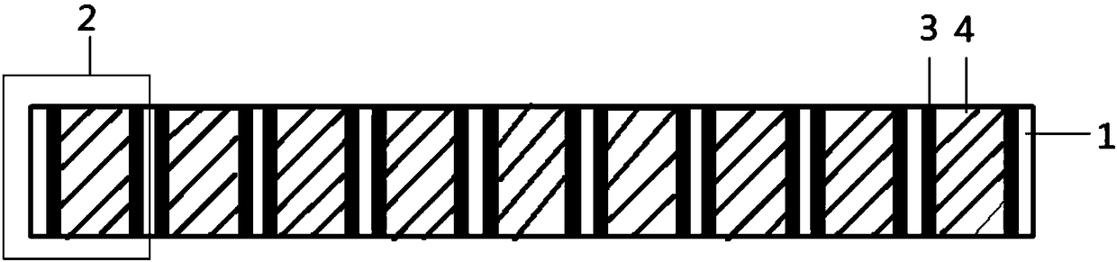
[0027] Through the combination of rods and tubes, wire drawing, plate arrangement, melting and pressing, and pickling, the microporous structure skeleton is obtained; the microporous structure skeleton includes a plurality of microporous skeleton units;
[0028] Depositing an optical fiber panel skin in the microporous skeleton unit by atomic layer deposition to obtain a base plate;
[0029] Melt the core material, place it on one end of the base plate and pressurize it to 0-5MPa, vacuumize the other end of the base plate until the vacuum degree is less than or equal to 1Pa, and fill the core material into the microscopic area of the base plate The inside of the hole is machined to obtain an infrared fiber optic panel.
[0030] Preferably, the pore diameter of the microporous skeleton unit is 4-50 μm, the concentricity is 10-20 μm, the p...
Embodiment 1
[0039] A kind of preparation method of infrared optical fiber panel that one embodiment of the present invention proposes, it comprises:
[0040] Through the combination of rods and tubes, wire drawing, plate arrangement, melting and pressing, and pickling, the microporous structure skeleton is obtained; the microporous structure skeleton includes a plurality of microporous skeleton units; the coaxiality of the microporous skeleton units is 10 μm, and the parallelism is 2 μm , with a flatness of 0.1 μm and a pore size of 4 μm.
[0041] The skin of the fiber optic panel is deposited in the microporous skeleton unit by atomic layer deposition to obtain a blank; the material of the skin of the fiber optic panel is ZnS with a thickness of 0.5 μm.
[0042] Heat the core material to 650°C to melt, place it on one end of the base plate, and evacuate the other end of the base plate until the vacuum degree is less than or equal to 10 -2 Pa, filling the core material into the micropore...
Embodiment 2
[0049] A kind of preparation method of infrared optical fiber panel that one embodiment of the present invention proposes, it comprises:
[0050] Through the combination of rods and tubes, wire drawing, plate arrangement, melting and pressing, and pickling, the microporous structure skeleton is obtained; the microporous structure skeleton includes a plurality of microporous skeleton units; the coaxiality of the microporous skeleton units is 10 μm, and the parallelism is 1 μm , with a flatness of 0.2 μm and a pore size of 25 μm.
[0051] Deposit the fiber optic panel cortex in the microporous skeleton unit by atomic layer deposition to obtain a blank; the fiber optic panel cortex material is ZnCl 2 , with a thickness of 2 μm.
[0052] Heat the core material to 680°C to melt, place it on one end of the slab and pressurize it to 3MPa, evacuate the other end of the slab until the vacuum degree is less than or equal to 1Pa, and fill the core material into the slab In the microhol...
PUM
 Abstract
Description
Claims
Application Information
 - R&D
- Intellectual Property
- Life Sciences
- Materials
- Tech Scout
- Unparalleled Data Quality
- Higher Quality Content
- 60% Fewer Hallucinations
Browse by: Latest US Patents, China's latest patents, Technical Efficacy Thesaurus, Application Domain, Technology Topic, Popular Technical Reports.
© 2025 PatSnap. All rights reserved.Legal|Privacy policy|Modern Slavery Act Transparency Statement|Sitemap|About US| Contact US: help@patsnap.com