Carrying device

A technology of carrying device and carrying parts, applied in vacuum evaporation plating, coating, thermoelectric device parts and other directions, can solve problems such as substrate cracking, and achieve the effect of rapid adsorption and separation

Inactive Publication Date: 2018-09-28
BOE TECH GRP CO LTD +1
View PDF6 Cites 3 Cited by
  • Summary
  • Abstract
  • Description
  • Claims
  • Application Information

AI Technical Summary

Problems solved by technology

Most of the existing equipment uses ordinary sticky objects to absorb the back of the substrate to reduce bending, but the substrate is prone to cracking when the substrate is separated

Method used


Image

  • Carrying device
  • Carrying device
  • Carrying device

Examples


Embodiment 1

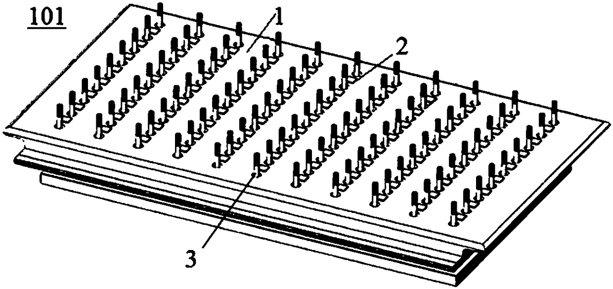
[0025] This embodiment provides a carrying device, figure 1 is a schematic structural diagram of the carrying device according to this embodiment.

[0026] like figure 1 As shown, the carrying device includes: a carrying part 1, which is used to carry the object to be supported. The object to be supported here is generally the substrate of the display device, and it can also be other devices. In the following description, the object to be supported is OLED The substrate is taken as an example, but the embodiment is not limited thereto; the adhesion element 2 is arranged on the carrying part, and the viscosity of the adhesion element is variable to realize the adhesion and separation of the object to be supported and the carrying device; The supporting member 3 is arranged on the carrying part and is used for supporting the object to be carried.

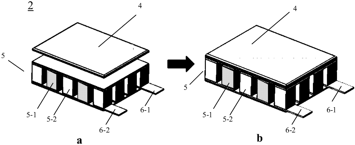
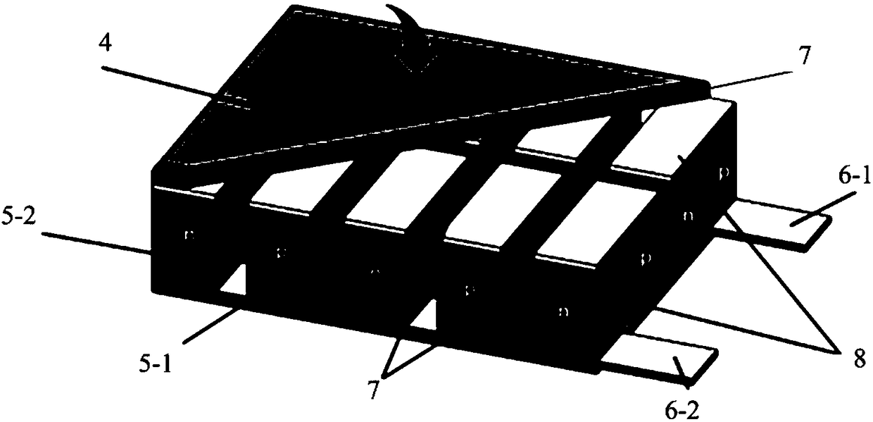
[0027] figure 2 is a schematic structural diagram of an adhesive element according to an embodiment of the present disclosure. ...


PUM


Abstract

The disclosure provides a carrying device comprising a carrying part for carrying a to-be-carried object, adhesive members arranged on the carrying part, and support members arranged on the carrying part. The adhesive members have the variable viscosity to realize attachment and separation between the to-be-carried object and the carrying device. The support members are used for supporting the to-be-carried object. According to the carrying device provided by the disclosure, attachment and separation of the substrate or the device are realized quickly in a vacuum environment.

Description

technical field [0001] The present disclosure relates to the field of display technology, in particular to a carrying device. Background technique [0002] In the prior art, the organic functional layers in organic light emitting diode (OLED) devices are mainly prepared by vacuum thermal evaporation. The evaporating material is stored in the crucible in the evaporating source, and the crucible is heated by the heater to sublimate the evaporating material, and the organic vapor is ejected from the injection mechanism and deposited on the evaporation surface of the substrate, forming a uniform organic film on the surface of the substrate. Most of the existing evaporation equipment adopts the form of the substrate evaporation facing downward, which can improve the utilization rate of materials and prevent dust particles generated during the evaporation process from falling on the evaporation surface. Existing equipment mostly uses ordinary sticky objects to absorb the back of ...

Claims


Application Information

Patent Timeline
Patent Type & Authority Applications(China)
IPC IPC(8): H01L21/687C23C14/50C23C14/24
CPCC23C14/24C23C14/50H01L21/68757H01L21/68785H01L21/67109H01L21/67706H01L21/67248H01L21/67253H01L21/6835H01L2221/68381H01L2221/68318C23C14/12C23C14/541H10N10/80H10N10/17H01L21/67346H10K71/80H10K71/164
Inventor 叶岚凯郭书鹏
Owner BOE TECH GRP CO LTD
Why Eureka
Try Eureka