
Radiator for electronic component

A technology for electronic components and radiators, applied in the field of electronic component radiators, can solve the problems of complex structure, short circuit, difficult to meet the needs of heat dissipation, etc., and achieve the effects of reducing heat source temperature, simple and compact structure, and improving heat dissipation efficiency.

Active Publication Date: 2018-09-28
JINGDEZHEN CERAMIC INSTITUTE
View PDF5 Cites 4 Cited by
  • Summary
  • Abstract
  • Description
  • Claims
  • Application Information

AI Technical Summary

Problems solved by technology

Among them, the air-cooled radiator is mainly composed of heat sinks and fans. The contact area and method of heat sinks and electronic components have affected the development trend of beautiful and light electronic equipment, and the power of the fans has also seriously increased the power consumption burden; and, based on With the continuous development of electronic technology, the heat flow of chips has increased sharply, and the traditional air-cooled heat dissipation method is becoming more and more difficult to meet the heat dissipation requirements.
The water-cooled radiator is more troublesome to install. If the liquid is exposed, it will cause a short circuit, which is dangerous
The heat pipe in the heat pipe radiator is a heat transfer element with extremely high thermal conductivity, which requires a fan to take away the heat, the structure is complex, and the price is relatively high.

Method used


Image

  • Radiator for electronic component
  • Radiator for electronic component
  • Radiator for electronic component

Examples


Embodiment

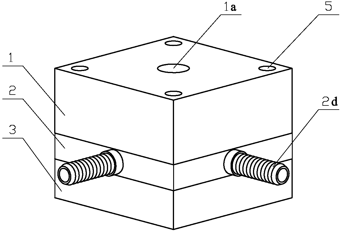
[0018] Figure 1 ~ Figure 4 Shown is the embodiment of a kind of radiator of electronic component of the present invention, as figure 1 As shown, it includes an upper air chamber part 1, a micro-jet hole part 2, and a lower mounting part 3 arranged sequentially from top to bottom to form a square column structure.

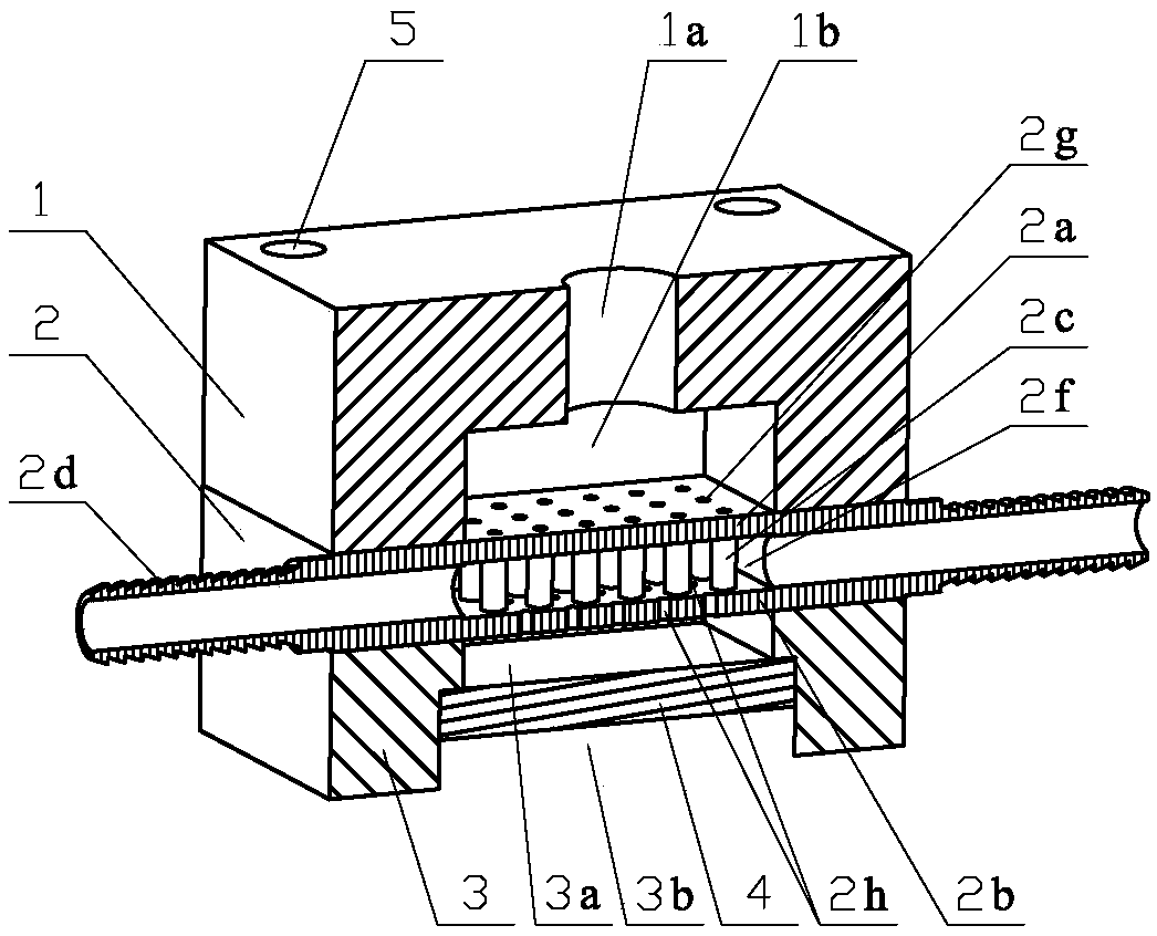
[0019] like figure 2 As shown, the middle part of the upper air chamber part 1 is provided with a fluid inlet 1a and an upper air chamber cavity 1b communicating with it.

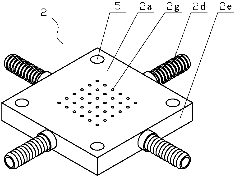
[0020] The micro-fluidic orifice 2 includes an upper micro-fluidic orifice plate 2a, a lower micro-fluidic orifice plate 2b, an airflow tube 2c, and a fluid outlet tube 2d. Wherein, the upper micro-fluidic orifice 2a is located in the upper air chamber cavity 1b, and is spaced apart from the lower micro-fluidic orifice 2b, and forms an orifice cavity 2f combined with the side 2e of the micro-fluidic orifice. The airflow pipe 2c is cylindrical, and is arranged side by side in the orifice cavi...


PUM


Abstract

The invention discloses a radiator for an electronic component. The radiator comprises an upper air chamber piece, a microjet hole piece and a lower mounting piece, which are sequentially stacked fromtop to bottom, wherein the upper air chamber piece is provided with a fluid inlet and an upper chamber cavity communicating therewith; the microjet hole piece comprises an upper microjet hole plate,a lower microjet hole plate, airflow pipes and fluid outlet pipes; the upper microjet hole plate is positioned at the upper chamber cavity and is spaced from the lower microjet hole plate to form a hole plate cavity in combination with the lateral surface of the microjet hole piece; the airflow pipes are arranged in parallel in the hole plate cavity and correspondingly communicate with microjet spray holes uniformly distributed in the upper microjet hole plate and the lower microjet hole plate; reflowing holes are also uniformly distributed in the lower microjet hole plate; the fluid outlet pipes are uniformly distributed on the lateral surface of the microjet hole piece and communicate with the hole plate cavity; an aluminum base is arranged in the lower mounting piece and is spaced fromthe lower microjet hole plate in parallel to form a jet cavity; and a mounting position for placing the electronic component is formed below the aluminum base. The radiator is simple and compact in structure and reasonable in design and the electronic component can be cooled more efficiently and safely.

Description

technical field [0001] The invention relates to the technical field of heat dissipation equipment, in particular to a heat sink for electronic components. Background technique [0002] In order to ensure that computers and other electronic equipment can work normally at a reasonable temperature, it is usually necessary to conduct contact heat dissipation and cooling of the heating end of the electronic component. At present, the heat dissipation equipment used in the prior art mainly includes: air-cooled radiators, water-cooled radiators, and heat pipe radiators. Among them, the air-cooled radiator is mainly composed of heat sinks and fans. The contact area and method of heat sinks and electronic components have affected the development trend of beautiful and light electronic equipment, and the power of the fans has also seriously increased the power consumption burden; and, based on With the continuous development of electronic technology, the heat flow of chips has increa...

Claims


Application Information

Patent Timeline
Patent Type & Authority Applications(China)
IPC IPC(8): H01L23/367H01L23/373H01L23/433H01L23/467
CPCH01L23/3672H01L23/3736H01L23/3737H01L23/4336H01L23/467
Inventor 孙健谢敏倩毛春林常学鹏袁水根
Owner JINGDEZHEN CERAMIC INSTITUTE
Learn More