Automatic processing apparatus used for track cable

An automatic processing and track technology, which is used in cable installation, cable installation devices, and equipment for dismantling/armoring cables, etc., can solve the problems of easy damage to the cable core, impact on cutting efficiency, low efficiency, etc., to extend service life, The effect of improving cutting efficiency

Active Publication Date: 2018-09-28
ANHUI CABLE
View PDF4 Cites 4 Cited by
  • Summary
  • Abstract
  • Description
  • Claims
  • Application Information

AI Technical Summary

Problems solved by technology

The main problems are low efficiency, easy damage to the cable core, high labor intensity, and inability to perform large-length stripping
In the cutting and peeling device proposed in the reference document (103683127B), the same cutting device is used when cutting the metal protective layer and the insulating layer, but because the strength of the metal protective layer material is much greater than the lightness of the insulating layer material , and when cutting at the same time, the cutting device is easy to get stuck with the metal protective layer, which will affect the cutting efficiency

Method used


Image

  • Automatic processing apparatus used for track cable
  • Automatic processing apparatus used for track cable
  • Automatic processing apparatus used for track cable

Examples


Embodiment 1

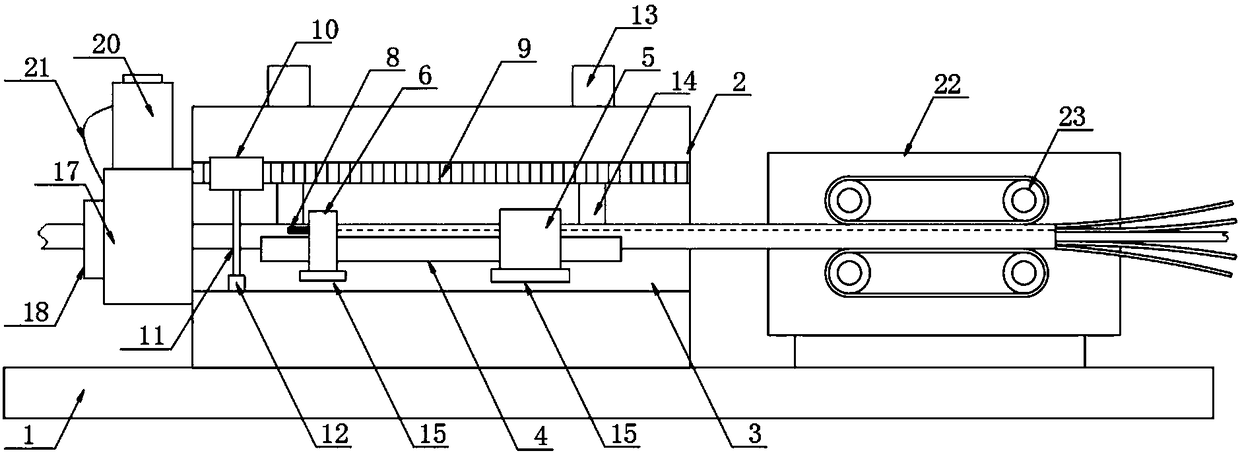
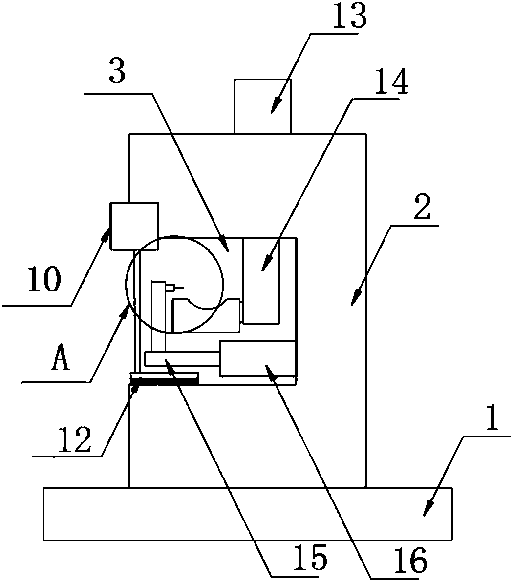
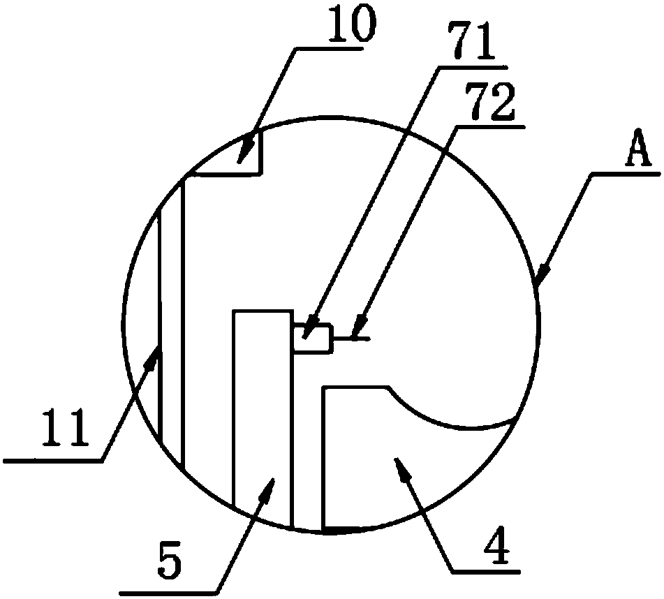
[0027] according to Figure 1-6 The shown automatic processing device for track cables includes a base 1 and a processing table 2, the processing table 2 is fixed on the top of the base 1, and a processing groove 3 is provided on one side surface of the processing table 2. Both ends of the processing tank 3 run through one end wall of the processing table 2 and extend to one side of the outer wall of the processing table 2. A conveying plate 4 is arranged inside the processing tank 3, and insulating parts are respectively installed at both ends of one side of the conveying plate 4. The connection plate 5 and the metal sheath connection plate 6, the insulation cutting device 7 is provided on one side of the connection plate 5, and the metal sheath cutting device 8 is provided on the one side of the metal sheath connection plate 6, the The insulating layer cutting device 7 and the metal sheath cutting device 8 are all arranged directly above the conveying plate 4, and the insula...

Embodiment 2

[0030] The difference with embodiment 1 is:

[0031]The first cylinder 13 is fixedly arranged on both sides of the top of the base 1, the bottom end of the first cylinder 13 extends to the inner cavity of the processing table 2, and the output end of the first cylinder 13 is provided with a first piston rod 14. A piston rod 14 runs through the top wall of the processing tank 3, and extends into the processing tank 3 to be fixedly connected to the side wall of the conveying plate 4. The bottom of the insulator cutting connecting plate 5 and the metal sheath connecting plate 6 are fixedly provided with a second Piston rod 15, the second piston rod 15 is arranged on the bottom end of the conveying plate 4, the other end of the second piston rod 15 is provided with a second cylinder 16, the output end of the second cylinder 16 is connected to the input of the second piston rod 15 The other end of the second cylinder 16 is fixedly arranged at the bottom of the side wall of the proc...


PUM


Abstract

The invention discloses an automatic processing apparatus used for a track cable. The automatic processing apparatus comprises a base and a processing table; the processing table is fixedly arranged on the top of the base; a processing groove is formed in one side surface of the processing table; the two ends of the processing groove run through the end walls of the processing table respectively,and extend to one side of the outer wall of the processing table; a conveying plate is arranged in the processing groove; and an insulating piece cutting connecting plate and a metal protection layerconnecting plate are arranged at the two ends of one side of the conveying plate respectively. By virtue of setting of an independent insulating layer cutting apparatus and metal protection layer cutting apparatus, and compared with the existing mode of cutting the insulating layer and the metal protection layer through one cutting apparatus, the cutting apparatuses of different strengths can be selected according to different strengths of the insulating layer and the metal protection layer, thereby improving cutting efficiency; and in addition, damage to the cutting apparatus in cutting can be lowered to the minimum, so that the service lives of the insulating layer cutting apparatus and the metal protection layer cutting apparatus are prolonged.

Description

technical field [0001] The invention relates to the field of track cable processing devices, in particular to an automatic processing device for track cables. Background technique [0002] In order to meet the requirements of electromagnetic field shielding and anti-mechanical damage in various complex environments, wire track cables are equipped with copper, aluminum, steel and other metal materials or other The metal shielding sheath composed of alloy materials, that is, the metal sheath of the track cable (also known as the metal sheath), the metal sheath is wrapped with various metal strips, longitudinally wrapped, welded into tubular or thin round wire wrapped and other structural forms are arranged on the outer layer of the track cable core. For the track cable with the metal sheath, in the process of manufacture, installation and maintenance, the metal sheath needs to be cut and peeled off, and then the track cable core should be detected, connected and installed. D...

Claims


Application Information

Patent Timeline
IPC IPC(8): H02G1/12
CPCH02G1/126
Inventor 张万有周俊夏候东韩俊宝高从民徐晓丽朱元忠陈安鹏
Owner ANHUI CABLE
Why Eureka
Try Eureka