
A circuit with dynamically adjustable current-limiting threshold

A technology of current limiting circuit and dynamic adjustment, applied in the direction of adjusting electrical variables, control/regulating systems, electrical components, etc., can solve problems such as reduction of inductor current

Active Publication Date: 2019-10-22
UNIV OF ELECTRONICS SCI & TECH OF CHINA
View PDF5 Cites 0 Cited by
  • Summary
  • Abstract
  • Description
  • Claims
  • Application Information

AI Technical Summary

Problems solved by technology

Due to some delay in the current sense loop, it is possible for the inductor current to drop to a negative value, which is usually undesirable

Method used


Image

  • A circuit with dynamically adjustable current-limiting threshold
  • A circuit with dynamically adjustable current-limiting threshold
  • A circuit with dynamically adjustable current-limiting threshold

Examples


Embodiment 1

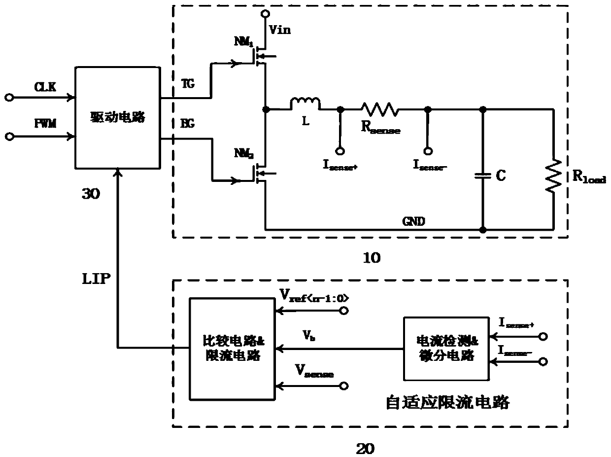
[0031] Such as figure 1 An adaptive current limiting circuit shown includes an adaptive current limiting circuit 20: a current detection & differential circuit, a comparison circuit & a current limiting circuit, a driving circuit 30 and a basic topology 30 of a buck switching power supply, including a power transistor NM 1 , NM 2 , inductance L, capacitance C and load resistance R load ; The input terminal V of the current detection & differential circuit module b connected to the sense resistor R sense On, the output terminal is connected to the input terminal of the comparison circuit & current limiting circuit module; the output signal Ctr of the comparison circuit respectively connected to the threshold control switch NM of the current limiting circuit module on; the output terminal LIP of the current limiting module is connected to the driving circuit.

Embodiment 2

[0033] Based on the principles of the foregoing embodiments, this embodiment takes n=2 as an example for detailed description.

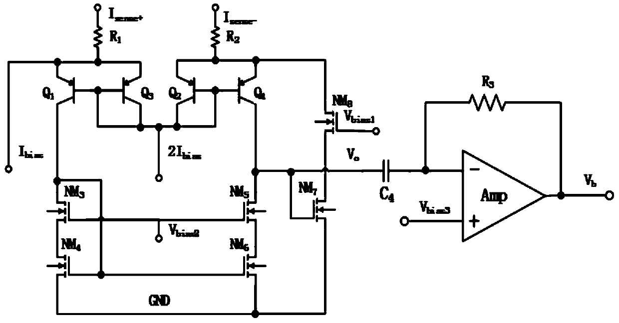
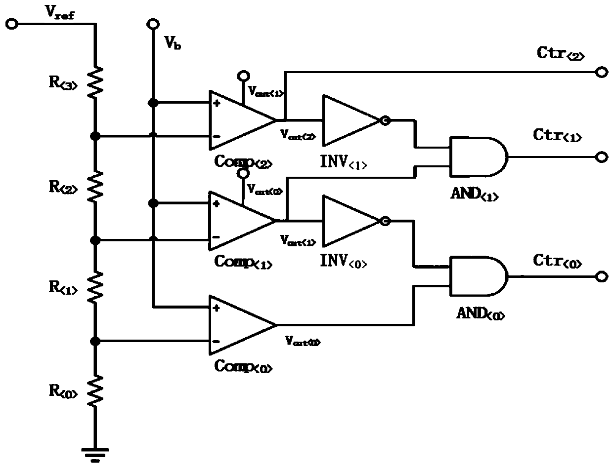
[0034] Such as figure 2 As shown, the current detection & differentiation circuit includes a transistor Q ;FET NM Resistance R Capacitance C 4 and operational amplifier Amp, its voltage and current bias as figure 2 shown. The current detection & differential circuit converts the abnormal change of the inductor current into a voltage V sense , and then convert the abnormal variation of the inductor current into the output voltage V through the differential circuit b . The voltage V by the comparator circuit b Quantized to three-bit control signal Ctr , the control signal realizes the adjustment of the dynamic threshold voltage by controlling the switch of the threshold voltage of the current limiting circuit.

[0035] The circuit for dynamically adjusting the current limiting threshold of the present invention also includes a driving c...


PUM


Abstract

The invention discloses a circuit with dynamically adjustable current-limiting threshold. The circuit includes: an adaptive current-limiting circuit connected to a driving circuit, and the adaptive current-limiting circuit is used for constantly monitoring the change of the inductor current. When an abnormal change in the current is detected, the system is adjusted in advance by appropriately increasing the threshold of the current limiting circuit to avoid a negative value of the inductor current; the driving circuit is connected to the basic topology of the buck, and the driving circuit is used It is used to process the PWM and CLK signals into drive signals TG and BG; the basic topology of the buck is matched with the drive circuit to convert the input voltage V in Reduce to the required voltage; through the real-time monitoring of the inductor current by the current detection circuit, differential circuit, and comparison circuit, the abnormal change of the inductor current is detected in advance and an appropriate current-limiting threshold is selected to prevent the inductor current from being negative first. to improve the overall performance of the system.

Description

technical field [0001] The invention relates to the field of power management, in particular to a circuit with a dynamically adjustable current limiting threshold. Background technique [0002] A switching power supply system usually includes some protection circuits, such as: temperature protection circuit, voltage protection circuit, circuit protection circuit. When an abnormality occurs in the switching power supply system, the protection circuit can protect the power supply system from being damaged. When the switching power supply system is abnormal or in a special mode, the inductor current will decrease rapidly. Due to some delay in the current sense loop, it is possible for the inductor current to drop to a negative value, which is usually undesirable. Contents of the invention [0003] In order to solve the above problems, this application proposes a circuit with dynamic adjustment of the current limit threshold, through the real-time monitoring of the inductor ...

Claims


Application Information

Patent Timeline
Patent Type & Authority Patents(China)
IPC IPC(8): H02M3/158
Inventor 阙隆成孟威威邓博李小飞周云
Owner UNIV OF ELECTRONICS SCI & TECH OF CHINA
Learn More