
Method of raising quantizing precision of pulse width modulation

A technology of pulse width modulation and quantization accuracy, which is applied to amplifiers with semiconductor devices/discharge tubes, amplifiers, electrical components, etc., and can solve problems such as reduced amplifier efficiency, harsh power devices, and increased noise shaping

Inactive Publication Date: 2002-04-17
CHINA AEROSPACE TIMES ELECTRONICS
View PDF0 Cites 2 Cited by
  • Summary
  • Abstract
  • Description
  • Claims
  • Application Information

AI Technical Summary

Problems solved by technology

But the following problems are: excessively increasing the oversampling multiple will make the requirements for power devices more stringent, and the efficiency of the amplifier will be reduced; and increasing the order of noise shaping will produce high-frequency oscillation and limiting distortion, and make high-frequency Poor sound quality

Method used


Image

  • Method of raising quantizing precision of pulse width modulation
  • Method of raising quantizing precision of pulse width modulation
  • Method of raising quantizing precision of pulse width modulation

Examples


Embodiment approach 1

[0111] Embodiment 1, such as Figure 7 Shown:

[0112] This embodiment applies the linear compensation method (the principle block diagram is shown in the appendix Figure 5 (c)) Application to realize 16-bit audio digital / analog conversion.

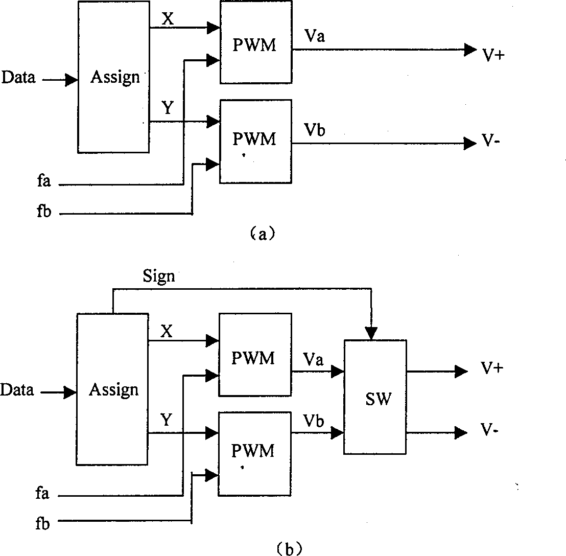
[0113] The dual-mode PWM quantizer involved in the present invention can be realized by a large-scale programmable gate array FPGA and peripheral analog circuits in this embodiment. The gate array model is EP20K100, and its interior is composed of 13 circuit units. P1 is a 16-bit subtractor, which performs the subtraction operation of the input 16-bit audio data Data and the error data e, where the error data e comes from the bus interface and is preset by the system according to the deviation caused by linear compensation. If there is no error in linear compensation, the error e is set to 0. P1 outputs 17-bit data, the highest bit is the sign bit. P2 is a complementary code circuit. When the sign bit is negative, the 16-bit data is...

Embodiment approach 2

[0114] Embodiment 2, such as Figure 8 Shown:

[0115] This embodiment applies the nonlinear compensation method (the principle block diagram is shown in the appendix Image 6 ) to realize the application of an all-digital audio power amplifier.

[0116] The dual-mode PWM quantizer involved in the present invention can be realized by a large-scale programmable gate array FPGA and peripheral analog circuits in this embodiment. The gate array model is EP20K100, and its interior is composed of 15 circuit units. P1 is a 16-bit subtractor, which performs the subtraction operation of the input 16-bit audio data Data and the error data, where the error data comes from the feedback branch and is dynamically generated by the nonlinear compensation algorithm. P1 outputs 17-bit data, the highest bit is the sign bit. P2 is a complementary code circuit. When the sign bit is negative, the 16-bit data is reversed and one is added, and then output, completing the absolute value circuit fu...


PUM


Abstract

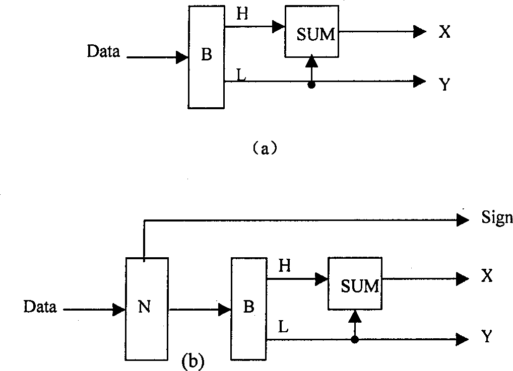
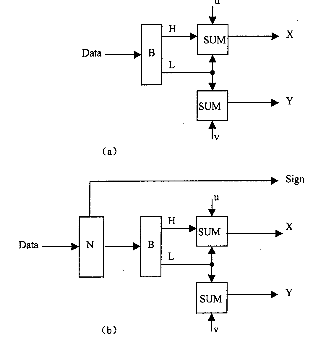
The invention discloses a new method for quantifying pulse width modulation, in order to provide higher quantifying precision at the condition of lower clock frequency. In the invention, an input data 'Data' with P bits is decomposed as a high position data H with m bits and a low position data L with n bits. Encoding the two data H, L forms data X and Y that are inputted to two PWM quantizers. The clocks of two PWM quantizers are fn and fb respectively. Expressions of output data passed of two PWM quantizers are X / k* (2 to the n power -1) and Y / k* 2 to the n power respectively. The above data conform to following relational expressino (1) m+n=p; (2) Data=2 to the n power *H+L; (3) fn=k* (2 to the n power -2) *fr, fb=k*2 to the n power *fr, here k is a constant, fr is data sampling frequency, n is a positive integer and its value equals to number of bits of data L. (4) Data / k * 2 to the n power * 2 to the n power -1)=X / k* 2 to the n power -1)-Y / k* 2 to the n power.

Description

technical field [0001] The invention belongs to the pulse width modulation of digital signals, and in particular relates to the pulse width modulation of digital signals by adopting a double-mode quantization method. Background technique [0002] The analog audio signal input by the class D amplifier is pulse-width modulated by the internally generated triangular wave to form a pulse signal output. Because the signal is continuous on the time axis, it is an analog power amplifier. [0003] When the current all-digital audio power amplifier performs pulse width modulation of digital signals, due to the limitation of semiconductor technology, the quantizer has low precision, resulting in a large output quantization noise. Therefore, the existing schemes all use increasing the oversampling multiple and increasing the order of noise shaping, so that the noise components in the audible frequency band are migrated out of the audible frequency band. But the following problems are...

Claims


Application Information

Patent Timeline
IPC IPC(8): H03F3/217
Inventor 马玉国
Owner CHINA AEROSPACE TIMES ELECTRONICS
Learn More