
Power grid direct supply-based high-power pulse power supply

A pulse power supply, high-power technology, applied in the direction of output power conversion devices, electrical components, etc., can solve the problems of low precision of thyristor half-controlled chopper adjustment, slow switching speed of current direction, high power quality requirements, etc., to achieve The effect of reducing size and volume requirements, increasing current output capability, and improving convenience

Inactive Publication Date: 2018-09-28
NAVAL UNIV OF ENG PLA +1
View PDF4 Cites 0 Cited by
  • Summary
  • Abstract
  • Description
  • Claims
  • Application Information

AI Technical Summary

Problems solved by technology

The three-phase uncontrolled rectification has high requirements on the power quality of the grid side, the power factor is low and the harmonics generated are high; the thyristor half-controlled chopper has low adjustment accuracy and poor current stability; the traditional degaussing station uses a knife The gate switch is used to change the direction of the output current. Since the knife switch is a mechanical switch, its action time is long, resulting in slow switching speed of the current direction, and the current direction cannot be changed at any time when the power is turned on. The human-computer interaction is poor.

Method used


Image

  • Power grid direct supply-based high-power pulse power supply
  • Power grid direct supply-based high-power pulse power supply
  • Power grid direct supply-based high-power pulse power supply

Examples


Embodiment Construction

[0022] In order to make the object, technical solution and advantages of the present invention clearer, the present invention will be further described in detail below in conjunction with the accompanying drawings and embodiments. The specific embodiments described here are only used to explain the present invention, not to limit the present invention. In addition, the technical features involved in the various embodiments of the present invention described below can be combined with each other as long as they do not constitute a conflict with each other.

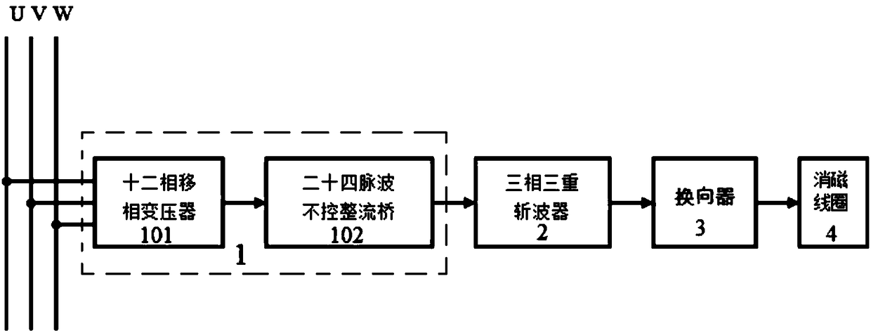
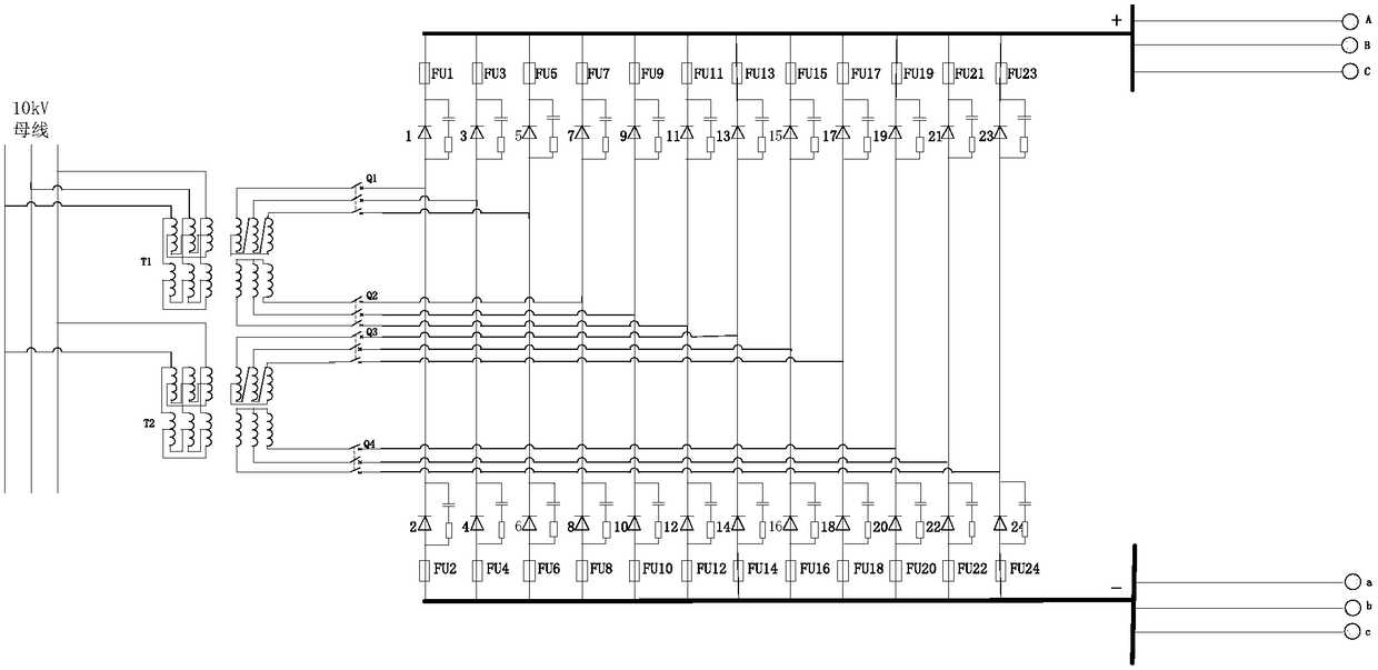
[0023] Such as figure 1 As shown, a high-power pulse power supply based on grid direct supply includes a 24-pulse uncontrolled rectifier 1, a three-phase triple chopping unit 2 and a commutation unit 3. This high-precision programmable power supply has three outputs, each of which The magnitude and direction of the current can be adjusted through the local operation terminal or the remote monitoring terminal. The input te...


PUM


Abstract

The invention relates to the technical field of electrical equipment, particularly a power grid direct supply-based high-power pulse power supply. The high-power pulse power supply comprises a 24-pulse wave uncontrollable rectifier, three-phase triple chopped wave units and a reversing unit, wherein the 24-pulse wave uncontrollable rectifier is used for converting the three-phase alternating current mains supply into three paths of direct current to be output to the three-phase triple chopped wave units; each three-phase triple chopped wave unit is corresponding to one path of direct current output of the 24-pulse wave uncontrollable rectifier, and used for converting the instable direct current voltage into a stable direct current voltage needed by a load and outputting the stable directcurrent voltage to one reversing unit separately; and the reversing unit is used for realizing reversing of positive and negative directions of the output current and outputting to a demagnetizing coil. By virtue of the high-power pulse power supply, the problem of current waveform distortion input on the grid side is solved, and the waveform quality of the output direct current voltage is ensured. Meanwhile, compared with a silicon controlled rectifier for rectifying, the 24-pulse wave uncontrollable rectifier improves the power factor of the apparatus, and in addition, direct current stability of a subsequent device is also ensured.

Description

technical field [0001] The invention relates to the technical field of electrical equipment, in particular to a high-power pulse power supply based on grid direct supply. Background technique [0002] In order to prevent warships from being threatened by underwater magnetic weapons and airborne magnetic detection, both at home and abroad pay more attention and put forward corresponding degaussing technology. The degaussing power supply is generally divided into two types of equipment, the main power supply and the auxiliary power supply. The output current of the degaussing main power supply is generally large, and it is in a certain regular decreasing pulse sequence. The output current of the auxiliary power supply is small, and the output current is constant, and the direction is adjustable. [0003] As an important part of the degaussing station, the degaussing auxiliary power supply system is mainly responsible for providing the compensation current required for the deg...

Claims


Application Information

Patent Timeline
IPC IPC(8): H02M9/06
CPCH02M11/00
Inventor 李志新赵文春周国华洪泽宏杨律郭成豹刘月林卿意武美娜刘娣孙建龙胡安胡石明潘京王文进
Owner NAVAL UNIV OF ENG PLA
Learn More