
Control device and system of single-stage multi-input grid-connected inverter

A control device and inverter technology, applied in single-grid parallel feeding arrangements, photovoltaic power generation, electrical components, etc., can solve problems such as practical limitations, poor grid-connected current waveform quality, and slow MPPT loop response speed.

Inactive Publication Date: 2020-08-07
XIAMEN UNIV OF TECH
View PDF0 Cites 0 Cited by
  • Summary
  • Abstract
  • Description
  • Claims
  • Application Information

AI Technical Summary

Problems solved by technology

[0004] The single-stage multi-input grid-connected inverter using the input power control method realizes the maximum power output of multiple new energy sources, but there is an obvious defect: because there is no control of the grid-connected current iL or the filter inductor current iLf (Note: iL=iLf), the quality of the grid-connected current waveform is poor, and due to the slow response speed of the MPPT loop, when the external conditions such as light intensity or wind speed change suddenly, it fails to cause a rapid response of the grid-connected current, resulting in an instantaneous power imbalance, and the grid-connected current Distortion occurs and damages the inverter
It can be seen that the single-stage multi-input grid-connected inverter adopting this control method has poor dynamic performance and weak anti-interference ability, and its practicability is greatly limited.

Method used


Image

  • Control device and system of single-stage multi-input grid-connected inverter
  • Control device and system of single-stage multi-input grid-connected inverter
  • Control device and system of single-stage multi-input grid-connected inverter

Examples


Embodiment Construction

[0036] The following will clearly and completely describe the technical solutions in the embodiments of the present invention with reference to the accompanying drawings in the embodiments of the present invention. Obviously, the described embodiments are only some, not all, embodiments of the present invention. Based on the embodiments of the present invention, all other embodiments obtained by persons of ordinary skill in the art without making creative efforts belong to the protection scope of the present invention.

[0037] In order to better understand the technical solutions of the present invention, the embodiments of the present invention will be described in detail below in conjunction with the accompanying drawings.

[0038] It should be clear that the described embodiments are only some of the embodiments of the present invention, not all of them. Based on the embodiments of the present invention, all other embodiments obtained by persons of ordinary skill in the ar...


PUM


Abstract

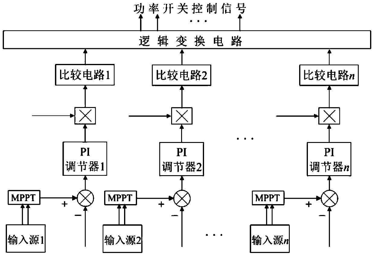
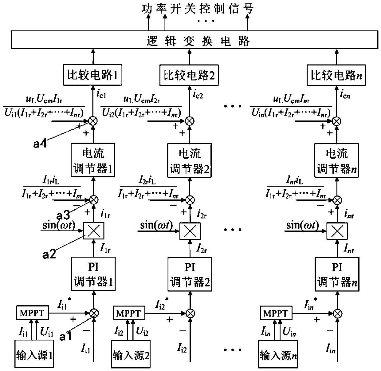
The invention provides a control device and system of a single-stage multi-input grid-connected inverter. The control device comprises: multiple paths of modulation circuits; an MPPT controller whichacquires the output current of the input source and generates the maximum power point current; a first operation node which operates the output current and the maximum power point current and then sends the output current and the maximum power point current to a PI regulator for amplification operation to form a first error amplification signal; a second operation node which generates the reference signal of the grid-connected current according to the first error amplification signal; a third operation node which receives the feedback signal and the reference signal of the grid-connected current and sends the feedback signal and the reference signal to the current regulator; a current regulator which calculates the first error amplification signal and generates a second error amplificationsignal; a fourth operation node receives the grid-connected voltage feedforward amount and operates with the second error amplification signal to generate a modulation signal of the input source; a logic circuit which generates a control signal according to the modulation signal and sends the control signal to the inverter, thereby realizing direct control of the grid-connected current, ensuringwaveform quality of the grid-connected current, and improving dynamic performance and anti-interference capability of the inverter.

Description

technical field [0001] The invention relates to the field of power electronics, in particular to a control device and system for a single-stage multi-input grid-connected inverter. Background technique [0002] Single new energy power generation systems such as photovoltaic cells and wind turbines usually have defects such as unstable power supply, discontinuity, and changes with climate conditions, which seriously affect the quality and efficiency of power generation. In order to improve the quality and efficiency of power generation, it is necessary to adopt a distributed power generation system that is jointly powered by multiple new energy sources. The single-stage multi-input grid-connected inverter can directly convert the energy of multiple same or different new energy sources into low-frequency alternating current and feed it into the AC grid. It has the advantages of simple circuit structure, single-stage power conversion, and high conversion efficiency. Distribute...

Claims


Application Information

Patent Timeline
IPC IPC(8): H02J3/38
CPCH02J3/38H02J2300/26Y02E10/56
Inventor 曾汉超邱琰辉郑雪钦彭民
Owner XIAMEN UNIV OF TECH
Learn More