Mixed coding method based on MIMO-OFDM millimeter wave structure

A hybrid coding, millimeter wave technology, applied in the field of hybrid coding based on MIMO-OFDM millimeter wave structure, to achieve the effect of reducing interference and significant performance advantages

Inactive Publication Date: 2018-09-28
DALIAN UNIV OF TECH
View PDF4 Cites 14 Cited by
  • Summary
  • Abstract
  • Description
  • Claims
  • Application Information

AI Technical Summary

Problems solved by technology

Most of the existing technologies focus on how to design hybrid precoding and combining matrices in narrowband. In addition, most of the existing millimeter-wave coding design algorithms are based on known channel for hybrid precoding design. When the channel information is unknown, how to design precoding is still need further research

Method used


Image

  • Mixed coding method based on MIMO-OFDM millimeter wave structure
  • Mixed coding method based on MIMO-OFDM millimeter wave structure
  • Mixed coding method based on MIMO-OFDM millimeter wave structure

Examples


Embodiment 1

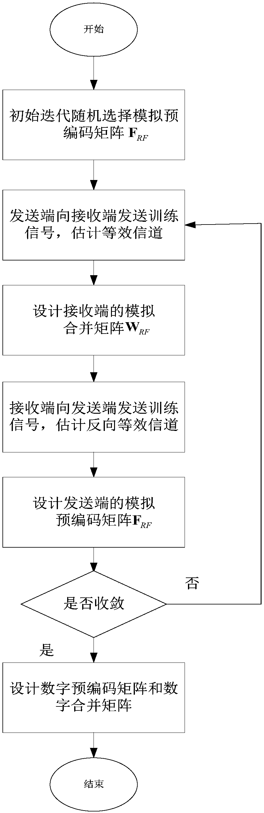
[0039] Example 1: Simulating the Merge Matrix Design

[0040] The transmitter first sends some training symbols for the receiver to estimate the forward channel. We assume that the different RF chains are independent of each other, and the training signals are transmitted by the RF chains one by one. The received signal of the k-th carrier on the i-th RF chain can be expressed as:

[0041]

[0042] The specific steps of estimating the effective channel are as follows:

[0043] S1: In the initial iteration, since the exact location of the receiver is not known, we use a random vector in each RF chain

[0044] S2: Define a dictionary Ψ r , the dictionary can cover the angle range from -900 to 900, then the equivalent channel of the first RF chain can be expressed as make Indicates the equivalent channel, X r [k] represents a sparse matrix.

[0045]

[0046]

[0047] Then, the equivalent channel can be expressed as

[0048]

[0049] S3: In order to obtain t...

Embodiment 2

[0067] Embodiment 2: Analog precoding matrix design

[0068] Using the resulting simulated merging matrix Channel Estimation of Reverse Channel and Design of Hybrid Precoding Matrix

[0069] Similar to the forward channel. The spectral efficiency of the reverse channel is expressed as

[0070]

[0071] in

[0072] S1: Because the receiving end simulates the combination matrix Known, the receiver also sends M t training samples to estimate the reverse equivalent channel. The signal received by the transmitter in the i-th RF chain can be expressed as

[0073]

[0074] make Indicates the reverse equivalent channel, Ψ t Represents the receiving dictionary, which is similar to the forward channel estimation process, and can be obtained

[0075] S2: After M r After training transmissions, the estimated signal of the kth carrier can be expressed as

[0076] R t [k]=Φ t (Y t [k]+N t [k])

[0077] = Φ t (Ψ( t x t [k]+N t [k])

[0078] =V t x t [k]+Φ ...

Embodiment 3

[0086] Embodiment 3: Design of digital precoding matrix and merging matrix

[0087] S1: After all analog beamformer pairs are determined, baseband digital precoding matrix and combining matrix are designed to further mitigate interference and maximize spectral efficiency. We can obtain the effective baseband channel

[0088]

[0089] S2: Perform singular value decomposition on the baseband channel

[0090]

[0091] u k and V k is a unitary matrix, Σ k is a diagonal matrix of singular values.

[0092] S3: The digital precoding matrix and the combination matrix can be expressed as

[0093]

[0094]

[0095] S4: Normalize the digital precoding matrix and the combination matrix

[0096]

[0097]

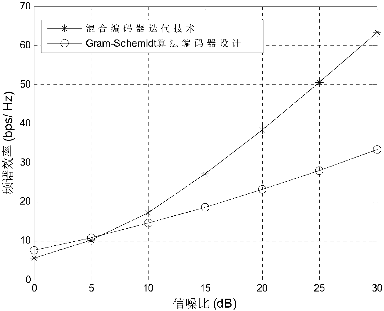
[0098] In order to further verify the performance and beneficial effects of the present invention, the present embodiment has carried out the following simulations:

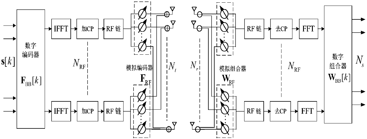
[0099] We consider a millimeter-wave MIMO-OFDM system with 32 antennas at both the transmitter a...


PUM


Abstract

The invention discloses a mixed coding method based on an MIMO-OFDM millimeter wave structure, and the method is used for designing a mixed pre-coding matrix and a combined matrix of a receiving end in an unknown channel scene, and comprises the following steps: S1, estimating a channel from the transmitting end to the receiving end; S2, designing a simulation combined matrix (shown in the description) of the receiving end; S3, carrying out the estimating of a channel from the receiving end to the transmitting end; S4, designing a simulation pre-coding matrix (shown in the description) of thetransmitting end: correspondingly selecting a vector, enabling all carrier gains to be maximum, from a codebook for a data stream transmitted by each RF, obtaining the simulation pre-coding matrix, and finishing the primary iteration; S5, taking the obtained simulation pre-coding matrix as a departure point, repeatedly executing the above steps S1-S4, and stopping the iteration till the number ofconvergence or iteration times exceeds a preset specified threshold value; S6, designing the digital pre-coding matrix and the combined matrix, and achieving the coding process.

Description

technical field [0001] The invention relates to the field of data control, in particular to a hybrid coding method based on MIMO-OFDM millimeter wave structure. Background technique [0002] With the progress of society and the development of science and technology, communication technology is constantly changing and improving people's living and working methods. mmWave communication achieves high data rate transmission by utilizing a large amount of unused bandwidth ranging from 30GHz to 300GHz. This makes mmWave an important solution to address spectrum congestion in future wireless communication networks. However, compared with traditional frequency bands, the propagation loss of millimeter wave bands will be more serious due to rain attenuation and low penetration. Since the wavelength of millimeter wave signals is very small, large arrays can be packaged into a small physical size. The combination of millimeter wave and massive MIMO communication systems can provide s...

Claims


Application Information

Patent Timeline
Patent Type & Authority Applications(China)
IPC IPC(8): H04B7/0456H04B7/06H04B7/08
CPCH04B7/0456H04B7/066H04B7/0842H04B7/0857
Inventor 李明刘雯菲刘倩
Owner DALIAN UNIV OF TECH
Why Eureka
Try Eureka