Optical waveguide

An optical waveguide and optical absorption technology, applied in the field of optical waveguides, can solve the problems of deterioration of S/N ratio, unstable optical communication, etc., and achieve the effect of improving the suppression of crosstalk

Inactive Publication Date: 2018-09-28
NITTO DENKO CORP
View PDF10 Cites 2 Cited by
  • Summary
  • Abstract
  • Description
  • Claims
  • Application Information

AI Technical Summary

Problems solved by technology

The light mixed into the adjacent core 2 is noise (N) to the light (signal S) propagating in the adjacent core 2, deteriorating the S / N ratio and destabilizing optical communication

Method used


Image

  • Optical waveguide
  • Optical waveguide
  • Optical waveguide

Examples


Embodiment 1

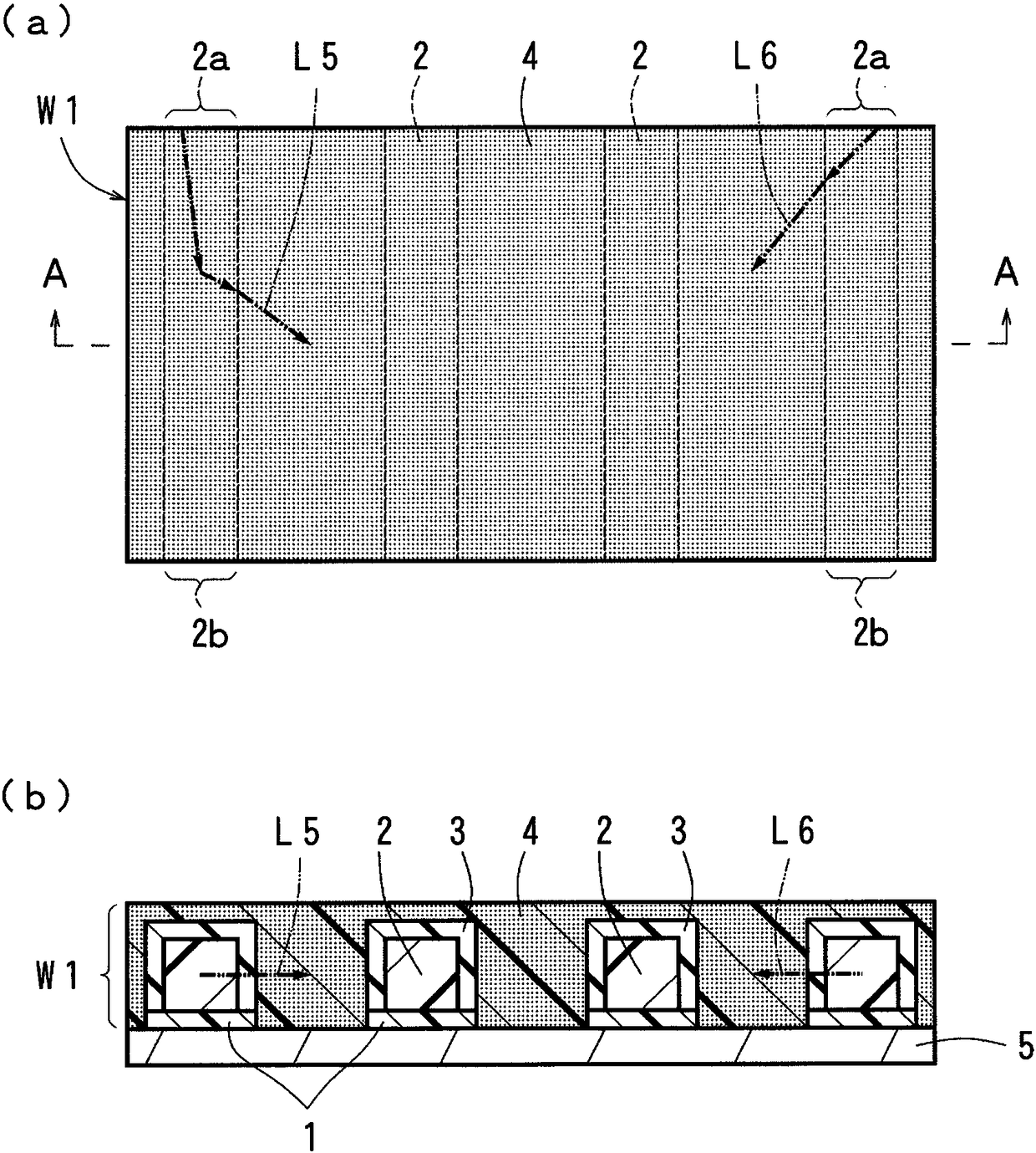
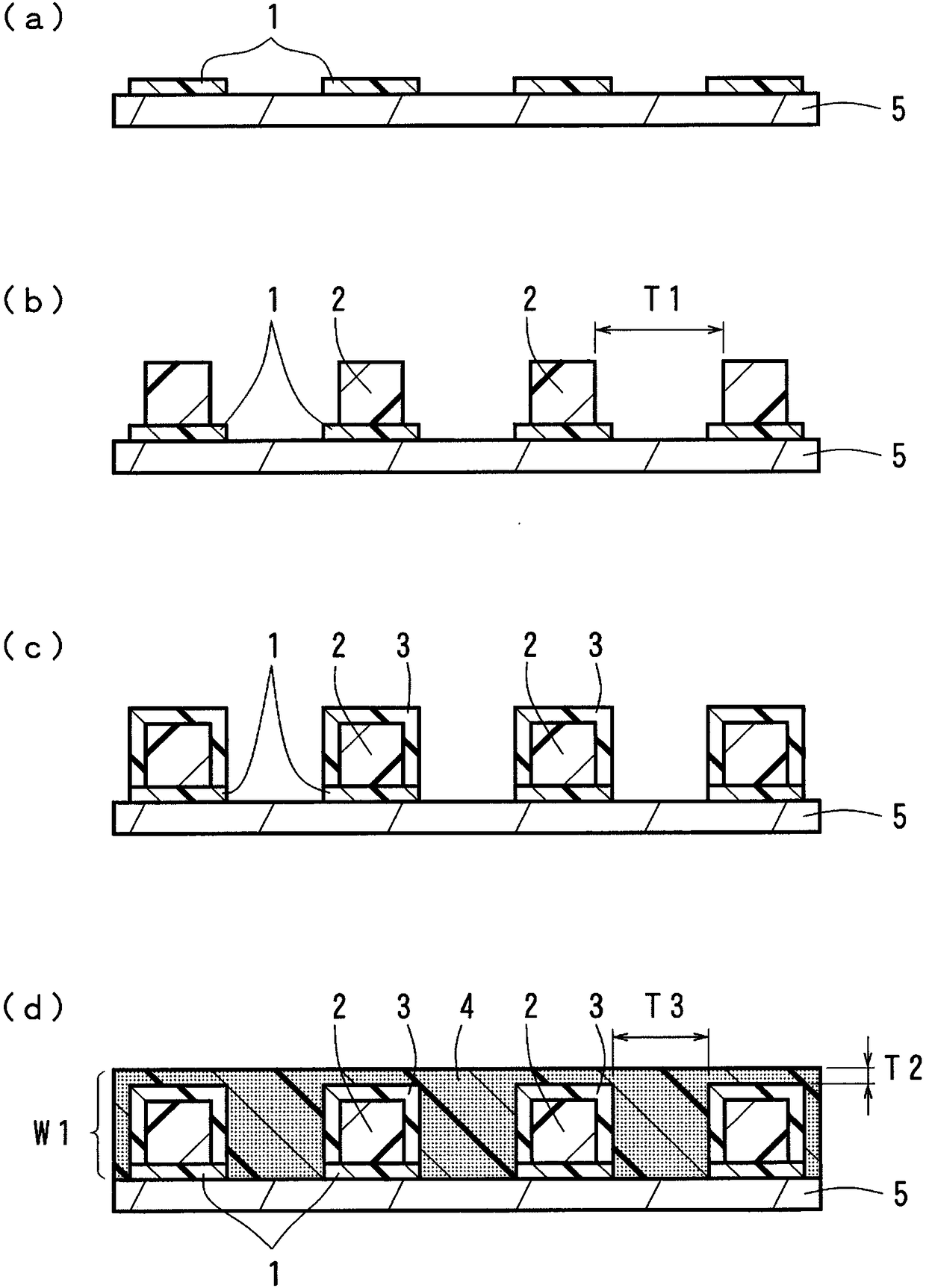
[0101] Using the above-mentioned forming materials, the surface of the resin substrate was fabricated such as figure 1 of (a), figure 1 The optical waveguide (50 mm in length) of the first embodiment shown in (b). Regarding the size of the under cladding layer, its thickness was set to 40 μm, its width was set to 100 μm, and the width of the gap between adjacent under cladding layers was set to 150 μm. Regarding the size of the core, the thickness was set to 40 μm, the width was set to 40 μm, and the formation pitch was set to 250 μm. The thickness of the overcladding layer was 30 μm for the portion covering the side surface of the core, and 30 μm for the portion covering the top surface of the core. Regarding the size of the light absorbing portion, the width of the portion sandwiched between the adjacent upper cladding layers was set to 150 μm, and the thickness from the top surface of the upper cladding layer was set to 15 μm.

Embodiment 2

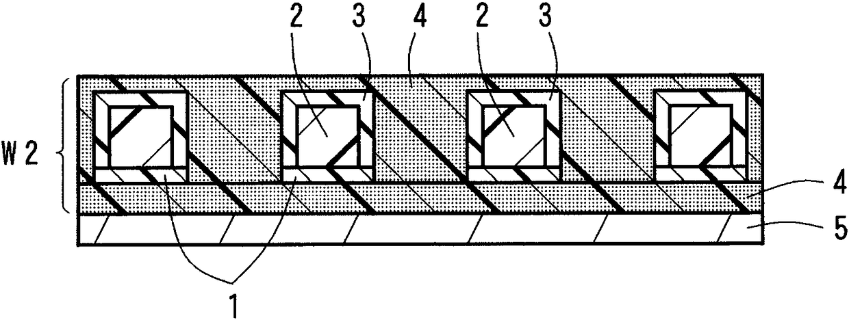
[0103] Fabricated on the surface of a resin substrate using the above forming materials image 3 The optical waveguide (50 mm in length) of the second embodiment shown. The thickness of the layer of the light absorbing portion provided between the under cladding layer and the substrate was set to 20 μm. The dimensions of other parts were the same as those of the first embodiment described above.

Embodiment 3

[0105] Fabricated on the surface of a resin substrate using the above forming materials Figure 5 The optical waveguide (50 mm in length) of the fourth embodiment is shown. Dimensions of structures such as a core were set to be the same as those in Example 1 above.


PUM


Abstract

The present invention provides an optical waveguide (W1) which is capable improving suppression of crosstalk. The optical waveguide (W1) is provided with: undercladding (1); a plurality of light propagating cores (2) which are arranged in parallel on the surfaces of the undercladding (1); overcladding (3) which covers the cores (2); and a light absorption part (4) which is provided among adjacentcores (2) in a state of non-contact with the cores (2). The light absorption part (4) includes a light absorption agent which has the ability to absorb light propagating inside the cores (2). The optical waveguide (W1) is prepared on the surface of a substrate (5).

Description

technical field [0001] The present invention relates to an optical waveguide used in the fields of optical communication, optical information processing and other general optics. Background technique [0002] as in Figure 13 As shown in top view in (a), as in Figure 13 (b) of Figure 13 As shown in the C-C sectional view of (a), the optical waveguide W13 usually protrudes in a predetermined pattern from the surface of the lower cladding layer 1 to form the linear core 2 for light propagation, and forms the upper cladding layer 3 in a state covering the core 2 . In addition, in the above-mentioned optical waveguide W13 , light is made to enter from the light incident portion 2 a at the first end of the core 2 and is emitted from the light emitting portion 2 b at the second end of the core 2 . That is, the light incident from the light incident portion 2a at the first end portion of the core 2 propagates in the core 2 to the second cladding layer while being repeatedly refle...

Claims


Application Information

Patent Timeline
Patent Type & Authority Applications(China)
IPC IPC(8): G02B6/122
CPCG02F1/225G02B2006/12097G02B2006/12126G02B6/125G02B6/136G02B6/132G02B6/122
Inventor 辻田雄一冈本宪彦
Owner NITTO DENKO CORP
Why Eureka
Try Eureka