A thermal expansion coefficient measurement device based on engineering thermophysics

A technology of thermal expansion coefficient and engineering thermophysics, which is applied in the field of engineering physics, can solve the problems of low measurement accuracy of the thermal expansion coefficient of the object to be measured, the inability to measure the thermal expansion coefficient of multiple objects at the same time, and the influence of the measurement of the thermal expansion coefficient of the object to be measured. The effect is good, the thermal expansion is uniform, and the effect of ensuring accuracy

Active Publication Date: 2021-03-23
SICHUAN UNIVERSITY OF SCIENCE AND ENGINEERING
View PDF8 Cites 0 Cited by
  • Summary
  • Abstract
  • Description
  • Claims
  • Application Information

AI Technical Summary

Problems solved by technology

[0009] (1) Due to the long size of the ejector rod and the holder, it is difficult to offset the expansion between the ejector rod and the holder during measurement, so that the measurement accuracy of the thermal expansion coefficient of the object to be measured is not high;
[0010] (2) The device for measuring the thermal expansion coefficient is generally long, which makes it difficult to ensure the uniform temperature in the device during measurement, which will have a certain impact on the measurement of the thermal expansion coefficient of the object to be measured;
[0011] (3) The existing thermal expansion coefficient measuring device can generally only measure one object at the same time, neither can measure the thermal expansion coefficient of multiple objects at the same time, nor can it quickly complete multiple measurements of the same object with the same size and take the average

Method used


Image

  • A thermal expansion coefficient measurement device based on engineering thermophysics
  • A thermal expansion coefficient measurement device based on engineering thermophysics
  • A thermal expansion coefficient measurement device based on engineering thermophysics

Examples


Embodiment Construction

[0039] The following will clearly and completely describe the technical solutions in the embodiments of the present invention with reference to the accompanying drawings in the embodiments of the present invention. Obviously, the described embodiments are only some, not all, embodiments of the present invention. Based on the embodiments of the present invention, all other embodiments obtained by persons of ordinary skill in the art without making creative efforts belong to the protection scope of the present invention.

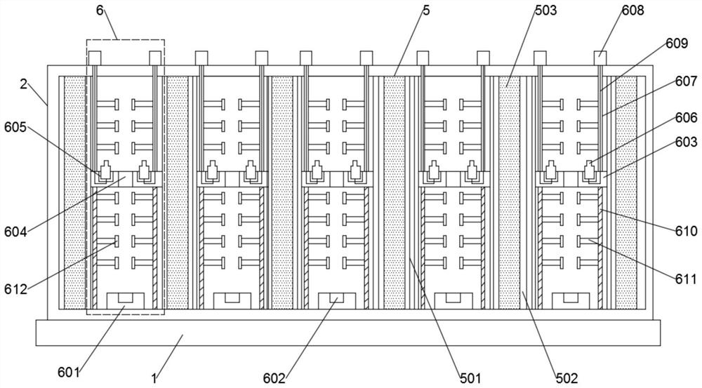
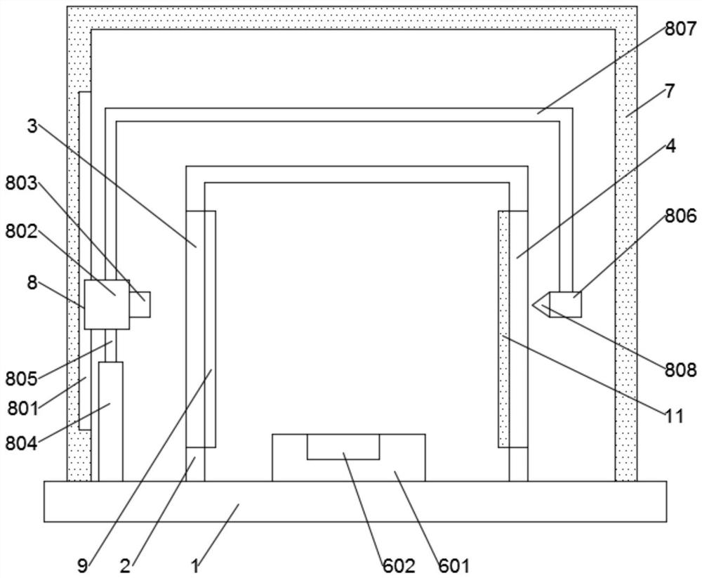
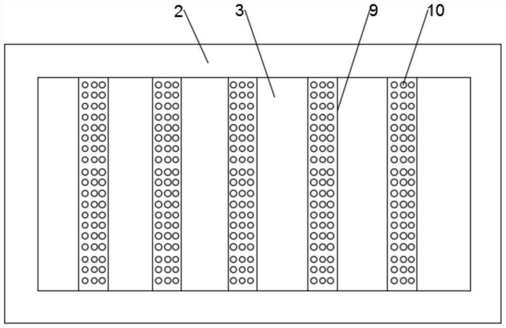
[0040] Such as Figure 1 to Figure 5 As shown, the present invention provides a thermal expansion coefficient measurement device based on engineering thermophysics, including a support base 1, a measurement housing 2 is fixedly installed on the top of the support base 1, and the front and rear ends of the measurement housing 2 are respectively arranged There are a front transparent glass layer 3 and a rear transparent glass layer 4, the front transparent glass...


PUM


Abstract

The invention discloses a thermal expansion coefficient measuring device based on engineering thermophysics. The thermal expansion coefficient measuring device comprises a support base, wherein a measuring shell is mounted at the top of the support base; a front transparent glass layer and a rear transparent glass layer are respectively arranged at the front end and the rear end of the measuring shell; a uniform heating mechanism is arranged inside the measuring shell; the uniform heating mechanism comprises heat conduction blocks which are arranged inside the measuring shell and are uniformlydistributed; holding cavities are formed inside the heat conduction blocks; electric heating plates are arranged inside the holding cavities; thermal expansion coefficient measuring mechanisms are arranged inside adjacent heat conduction blocks; a gantry is arranged outside the measuring shell; an adjusting photographing mechanism is arranged on the gantry. By adopting the thermal expansion coefficient measuring device, measurement of an object to be measured can be prevented from being affected by a measuring structure, meanwhile, temperatures inside the device can be uniformly distributed,the precision of measurement results can be ensured, in addition, thermal expansion coefficients of multiple objects can be simultaneously measured, multiple times of measurement can be carried out toobtain an average value, and thermal expansion coefficients of multiple objects can be simultaneously measured.

Description

technical field [0001] The invention relates to the field of engineering physics, in particular to a thermal expansion coefficient measuring device based on engineering thermophysics. Background technique [0002] Engineering physics is a combination of the three disciplines of physics, engineering and mathematics. The combination of basic physics with the problems to be solved and engineering techniques makes engineering physics have a wide range of applications. This interdisciplinary subject is set up for continuous invention in the field of technology. Unlike traditional engineering disciplines, engineering science / physics does not need to be limited to a branch of science or physics. And engineering science / physics refers to a specialization such as optics, quantum physics, materials science, applied physics, nanotechnology, micromanufacturing, mechanical engineering, electrical engineering, biophysics, control theory, aerodynamics, energy, solid state Physics, etc. p...

Claims


Application Information

Patent Timeline
Patent Type & Authority Patents(China)
IPC IPC(8): G01N25/16
CPCG01N25/16
Inventor 梁超黄华司马卫平廖熠唐恒军
Owner SICHUAN UNIVERSITY OF SCIENCE AND ENGINEERING
Why Eureka
Try Eureka